


ELECTRO-VOICE
®
X-Line Very Compact
TM
Rigging Manual39
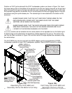
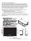
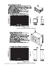
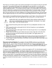
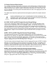
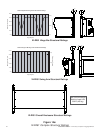
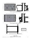
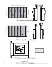
Each Figure 13 includes a graph of the working-load weight-versus-angle limit rating for the XLVC
enclosures. This working-load weight limit is applicable to every enclosure in an array, and in-
cludes the weight of that enclosure plus the total weight of all enclosures, rigging hardware and
cabling suspended below it. The enclosure elevation angle is the vertical angle of that enclosure,
where 0° represents an upright enclosure facing straight ahead (0° elevation angle). These work-
ing-Ioad-versus-angle limits take into account the complex forces generated in the front hinge
bars, the rear swing arms, the quick-release pins, the rigging tubes and channels, the enclosures
and the (optional) pull-up line, as a result of the complex weight distribution throughout the array.
Also included in the simplified structural-rating guidelines in each Figure 13 are side-to-side and
front-to-back angle limits for the front hinge bars and rear swing arms on the top enclosure.
WHEN APPLYING THE SIMPLIFIED STRUCTURAL RATING GUIDELINES TO
ANY XLVC LOUDSPEAKER SYSTEM SUSPENDED OVERHEAD, THE USER
MUST OBEY THE FOLLOWING RULES:
1. Never exceed the working-load-versus-angle limit for any loudspeaker enclosure in the
array.
2. Never exceed the side-to-side angle limits for the front hinge bar on any loudspeaker
enclosure in the array.
3. Never exceed the side-to-side angle limits for the rear swing arm bar on any loudspeaker
enclosure in the array.
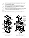
4. Always make sure that two quick-release pins secure every hinge bar at the side of the
enclosures and grids and that those pins are fully locked in the rigging tubes on all
enclosures and grids.
5. Always make sure that the quick-release pins for every swing arm pass through the hole in
the swing arm and are fully locked in the rigging channels on all enclosures and grids.
6. If a pull-up grid is used at the bottom of the array, never exceed the side-to-side angle limits
for the pull-up grid.
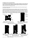
Discussion of Array Examples: For example, if the top XLD281 enclosure in a column was
angled down 55°, the enclosure working-Ioad-versus-angle limit from the simplified structural-
rating guidelines shown in Figure 13a would indicate that a total of 840 pounds (381 kg) could be
safely suspended. This would include the weight of the top enclosure plus all of the enclosures
and rigging suspended below.
If, however, the top XLD281 enclosure in a column was angled up 55°, the total allowable weight
would then only be 741 lb (336 kg) - including the weight of the top enclosure plus all of the enclo-
sures and rigging suspended below. The enclosure working-load-versus-angle limit shown in
Figure 13 not only applies to the top enclosure in an array column, but also applies to every enclo-
sure in an array column. In arrays where a pull-up grid is not used, the top enclosure is always the
limiting factor because it supports the most weight. However, in arrays where a pull-up grid is used
to achieve substantial downward angles, it is possible that a lower enclosure could be the limiting
factor.