


ELECTRO-VOICE
®
X-Line Very Compact
TM
Rigging Manual 28
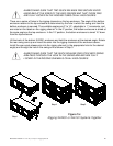
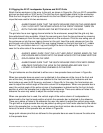
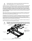
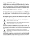
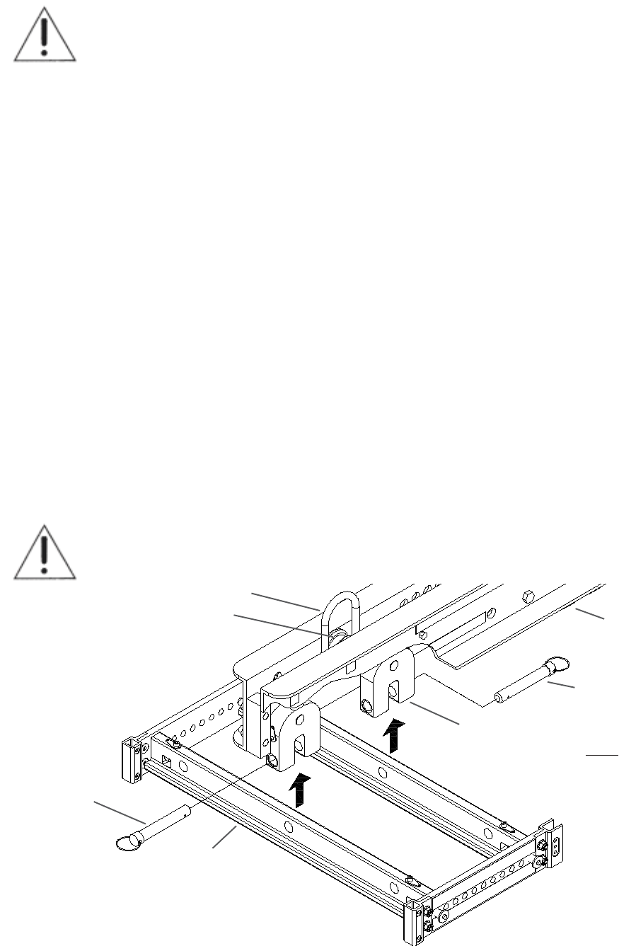
Figure 9a:
CBEAM Rigging Assembly
Pickup Ring
Centering Ring
Quick-Release
Pin
Grid
Quick-Release
Pin
Yoke
Coupler Beam
Note: Coupler Beam
shown cutaway for better
conceptualization and
clarity.
ALWAYS MAKE SURE THAT EACH QUICK-RELEASE PIN SECURING EACH
GRID SPREADER BAR IS FULLY LOCKED IN EACH YOKE.
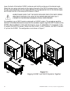
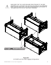
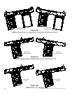
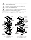
As shown in Figure 9d, the CBEAM may be picked up using one pickup point or two pickup points.
The two pick up points may be raised and lowered as necessary to adjust the vertical tilt angle.
When using two pick up points, the pickup rings are usually installed in Holes #1 and #30 at the
extreme ends of the CBEAM for maximum front-to-back stability. However, the pickup rings may
be relocated to redistribute the load between the front and back points. In Holes #1 and #30 can
only accommodate tilt angles of up to 30° before the rings will contact the spacer bars in the beam
assembly. When greater tilt angles are required, the pickup points should be moved towards the
center of the CBEAM.
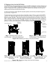
When using one pickup point, the vertical tilt of the array can be adjusted by changing the hole in
which the pickup ring is installed in the CBEAM. The LAPS program can be used to determine
which hole to use to achieve the desired vertical angle.
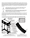
Each pickup ring has a centering ring. The centering ring positions the pickup ring in the center of
the CBEAM slot so that array will hang straight and not tilt sideways. To relocate the pickup ring,
remove the cotter pin from the clevis pin and remove the clevis pin from the beam assembly.
Move the pickup ring and centering ring to the desired hole and reinstall the clevis pin in the beam
assembly holes, then secure the clevis pin with the cotter pin.
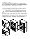
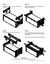
For Shipping/Transport, the yoke and ring assemblies may be installed in the beam assembly, as
shown in Figure 9e, so that all moving parts are recessed.
MAKE SURE THAT THE EACH CLEVIS PIN SECURING EACH PICKUP RING TO
THE BEAM IS LOCKED IN POSITION BY THE COTTER PIN. DO NOT LIFT ANY
ASSEMBLY OVERHEAD WITHOUT A COTTER PIN TO LOCK EACH CLEVIS PIN.