


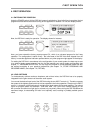

3. INSTALLATION AND CONNECTIONS
Correct connections is a vital factor in achieving the best results with the DSP 244. Before switching on
the power you have to connect the supplied European standard mains cord to the DSP 244 and your
mains wall outlet. The power supply unit of the DSP 244 automatically adapts to supply voltages in a
range of 90 to 250 VAC, so that the appliance can be operated with different, country-specific mains
voltages.
To prevent any trouble occurring from high temperatures inside the appliance, it is advisable not to use
the DSP 244 in environments with ambient temperatures exceeding 40°C; sufficient air-flow is also always
important. One HU is necessary for rack-installation. Normally, in this case, there are no special measures
for ventilation necessary. Like with any other LF-signal processing unit, it is not recommended to install
or operate the DSP 244 directly above or below any device that generates a massive magnetic field; e.
g. power amplifiers. In this way the risk of unwanted interference is reduced to a minimum.
Before switching the DSP 244’s power on, make sure that all necessary connections have been
established. So, make the required input and output connections in advance and in accordance to the
desired configuration.
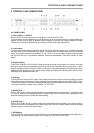
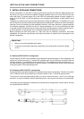
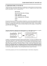
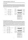
3.1 Balanced INPUT/OUTPUT configuration
For best results, the DSP 244 is operated using its balanced inputs and outputs. In this configuration, the
cable’s non-inverting conductor (+) needs to be assigned to pin 2 of the XLR-type connector while the
inverting conductor (-) is assigned to the connector’s pin 3. The shielding has to be connected to pin 1. If
the input channels supply transformers for galvanic isolation, the cable screen should not be connected
to the ground plain of the transmitting device.
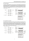
3.2 Unbalanced INPUT/OUTPUT configuration
It is also possible to operate the appliance in unbalanced input/output configuration. Therefore, the cable’s
“HOT” conductor has to be connected to pin 2 and the screen to pin 1 of the XLR-type connector.
To prevent the level being attenuated by 6dB, you have to short-circuit pins 1 and 3 of the XLR-type
connector. In case this measure leads to interference noise, removing this connection is recommended.
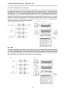
The following shows examples for balanced and unbalanced pin-assignments of audio cables, like they
can be used with the DSP 244.
IMPORTANT:
• Always use correctly shielded audio cables.
• To prevent loosing treble frequencies, especially input cords should not exceed a length
of 10 m
INSTALLATION AND CONNECTIONS
3-1