


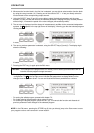
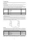
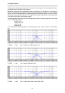

MASTER DELAY
These delay lines are located in the inputs IN1, IN2 and in the summed input signal IN1+2; all x-over
channels are affected.
For instance, this allows to feed different PA-towers at open air concerts with delayed signals.
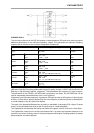
The delay times are displayed in milliseconds and microseconds while the equivalent distances (unit) are
displayed in feet, inches, meters or centimeters. The environmental temperature appears as additional
parameter whenever distances are displayed. Thus, up to 3 parameters are available.
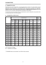
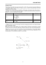
Parameter Settings / Value range
Default
Delay
2 ms - 900 ms
1927 µs - 900000 µs
2 feet - 1014 feet
26 inch - 12169 inch
1 m - 309 m
66 cm - 30910 cm
2 ms
Unit ms, µs, feet, inch, m, cm ms
Temp
-20°C - 60°C
-4°F - 140°F
20°C
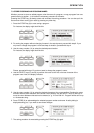
The Delay parameter determines the delay time of the corresponding channel or the distance between
different loudspeaker clusters.
Unit allows the user to select between time or distance display. Distances are automatically converted
into delay times plus the calculation additionally includes the influence of the environmental temperature.
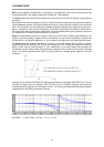
Temp allows you to enter a value for the momentary environmental temperature. This parameter appears
only when the selected display-unit is distance. The affect of the environmental temperature on the
resulting delay time is automatically included in the calculation.
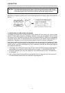
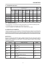
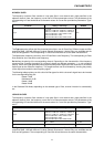
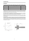
ROUTING
Any combination of input channels can be assigned to the outputs of the DSP 244. The routing defines
which input signal is fed to either one of the output channels (OUT1, OUT2, OUT3, OUT4). Besides routing
the signals of the two input channels IN1 and IN2 to one of the outputs, it is also possible to assign the
summed, monaural audio signal of both inputs IN1+2 to one of the outputs.
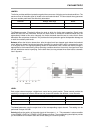
Parameter Settings / Value range
Default
Source IN1, IN2, IN1+2
IN1 (OUT 1/2)
IN2 (OUT 3/4)
Label
SUB, LO, MID, HI,
LO-MID, LO-MID-HI,
SUB-LO-MID-HI
SUB
Label allows the setting of the channel-function indicators - SUB, LO, MID, HI - on the front panel of the
appliance. These LEDs indicate the individual frequency range which the corresponding channel is
actually configured for. The LEDs are meant for indication purposes only - no parameters are changed.
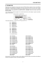
PARAMETERS
8-6