


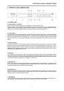
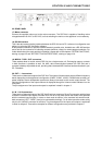
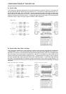

2.2 REAR PANEL
17, Mains connector
Connect the supplied mains cord to the mains connector. The DSP 244 is capable of handling mains
voltages between 90 V AC to 250 V AC, so that switching the mains on the appliance is not necessary.
18, RS-232 Interface
This is the data communication interface between the DSP 244 and a PC. It allows unit configuration and
editing by using the DSP 244 Editor software.
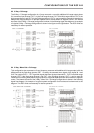
At this position installation of optional interface boards is possible, also. Available are: a RS-485 interface
and a card for the connection of switching contacts (switches, relays) for remote program selection. For
further details about the cards and their installation, please refer to the chapters “OPTION FUNCTIONS”,
starting on page 9-5 and “RETROFITTING INSTRUCTIONS”, starting on page 10-6.
19, MIDI IN / THRU / OUT connectors
These sockets allow to control several DSP 244 via a single master unit. Exchanging memory contents
in both directions is possible as well. Via MIDI, data communication between the DSP 244 and a
computer’s desktop is possible as well, providing that a standard MIDI-interface has been installed in your
PC / Notebook.
20, OUT 1 - 4 connectors
These are the 4 balanced outputs of the DSP 244. The signals of these sockets supply different frequency
bands, depending on the appliance’s configuration (2-WAY, 3-WAY, 4-WAY). Please make sure that your
power amplifiers and/or loudspeaker systems are always connected to the correct output channel. The
individual configuration of the output channels is displayed through the “channel status indicators” on the
front panel.
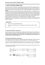
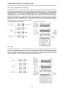
The pin-assignment of the inputs and outputs is explained in detail in chapter 3.
21, IN 1 / IN 2 connectors
These are the 2 balanced inputs of the DSP 244. Each input employs a Direct Out connector which allows
to feed the unaltered input signal to another DSP 244 or to any other device that needs to be operated
with the unaltered source signal. In stereo or dual mode as well as in the monaural sub woofer mode,
both connectors (LEFT / RIGHT) have to be connected accordingly. For all other operation modes using
only the IN 1 (MONO) connector is sufficient. The pin-assignment of the inputs and outputs is explained
in detail in chapter 3. Connection-examples for different configurations are provided in chapter 6.
CONTROLS AND CONNECTIONS
2-3