


Gain sets the degree of amplification or attenuation of the parametric EQ or the low shelving and high
shelving equalizers. The setting is performed in steps with 1 dB-stepwidth.
The Slope parameter describes the steepness or order of the filter for the low shelving or high shelving
equalizers.
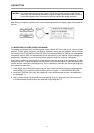
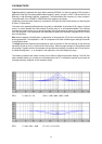
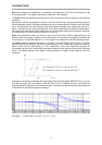
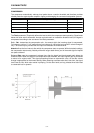
By setting the low shelving equalizer’s slope to 12 dB and the filter frequency to the resonance frequency
of the loudspeaker cabinet, the Slope parameter also lets you create a special LPN filter (Low Pass Notch
filter). This is possible, since the frequency response of speaker cabinets’ lower frequencies drops by 12
dB/oct., starting from their resonance frequency. A LPN filter compensates and shifts this polarization in
the transmission down towards lower frequencies. The picture below shows typical frequency responses
of a cabinet with LPN filter (A) and one without LPN filter (B).
Slope also describes the filter curve of the Lo-Pass and Hi-Pass filters. Different slope settings for the
transition band are possible. Together with the Q-parameter this provides the possibility to program the
Hi-Pass filter for so called B6-alignment; i. e. an increase in the response in the cutoff frequency range.
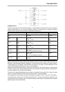
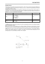
The Order parameter determines whether a 1st order or 2nd order Allpass filter is used. A 1st order
Allpass filter shifts the phase by 180° and its cutoff frequency is 90°. A 2nd order Allpass filter shifts the
phase by 360° and its cutoff frequency is 180°. Additionally, a 2nd order Allpass filter provides the
Q-parameter (quality) which allows setting the phase response of the transition range (lower Q-settings
result in flat phase response while higher Q-settings produce a steeper phase response; see also
examples).
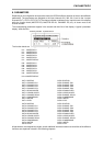
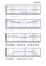
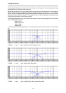
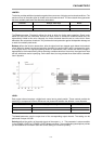
Examples for the settings of different filter types are provided in the paragraph MASTER EQ1-5. You are
also able to program your own settings of the DSP 244 via PC or notebook computer and monitor the
resulting frequency response on the computer screen. The following example shows the phase response
of Allpass filters with different parameter settings.
ALLPASS: f = 1kHz, Order = 1st, 2nd Q = 0.7, 1.0, 2.0
PARAMETERS
8-8