


8, STORE-key
This key allows the user to store edited programs in one of the user-definable program presets (U01 -
U30) or to copy programs from one preset to another. For further information, please refer to chapter 7.4,
“STORE PROGRAMS AND PROGRAM NAMES”.
9, RECALL-key
Pressing this key lets you enter the PROGRAM SELECTION mode where you can select factory or
user-definable program presets through using the rotary encoder. By pressing the RECALL-key, the
selected program is acknowledged and gets loaded.
For further information, please refer to chapter 7.1, ”PROGRAM SELECTION”.
10, Rotary encoder with push-button function
While in PROGRAM SELECTION mode, rotating the encoder selects the desired program. It is activated
by pressing the RECALL-key. In EDIT mode, the encoder lets you alter parameter setting or leaf through
function blocks. Simultaneously dialing the encoder while keeping it pressed increases the speed in which
the parameter values are changed. For further details, please refer to the chapter “OPERATION” starting
on page 7-1.
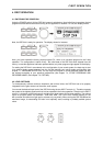
11, OUTPUT-controls 1 - 4
These rotary controls are used to set the output levels of channels 1 to 4, allowing to match the DSP 244
to the input levels of the devices chained in sequence. Correctly setting these controls results in an
improved S/N ratio. In most cases, good results are achieved when setting the controls to their center
position (-6). The digital output gain control should be used when higher output levels are needed. Use
the rotary controls OUTPUT 1 - 4 to attenuate the output levels. It is not recommended to use the digital
output gain control for massive attenuation, since this would decline the dynamic range of the D/A-con-
verters.
The rotary controls also provide push-button-functionality, which, in the EDIT mode is used to switch
between function blocks, channel-related; i. e.: pressing a rotary control switches to the corresponding
output channel. For further details, please refer to chapter 7.2, “EDITING”.
12, MUTE-keys 1 - 4
These keys allow to mute the output signal of the corresponding output channels. Pressing a key once
switches the mute-function ON; the key’s red LED lights. Pressing the button again switches the
mute-function OFF; the key’s LED is dimmed again.
13, Channel function indicators SUB, LO, MID, HI
These LEDs indicate, which frequency band the corresponding channel is set to. If a channel is configured
for full range operation, all its function-LEDs are simultaneously lit.
14, Level meter indicators OUTPUT 1 - 4
These LEDs indicate the peak level of the corresponding outputs. The DSP 244 should be operated in a
range, so that the clip-LEDs are not lit. Otherwise, this could lead to internal clipping. The indicators can
be set to “Peak-Hold” or “Slow-Mode”.
15, Compressor indicators OUTPUT 1 - 4
The COMP-LEDs light, when the compressor / limiter of the corresponding channel is activated; e. g.:
when the audio signal level exceeded the previously set threshold and therefore the output level is
compressed or limited.
16, POWER ON/OFF-switch
This switch turns the DSP 244’s mains power on or off.
CONTROLS AND CONNECTIONS
2-2