


10.3 RETROFITTING INSTRUCTIONS
CAUTION: These servicing instructions are for use by qualified personnel only. To reduce the
risk of electric shock, do not perform any servicing other than that contained in the
Operating Instructions unless you are qualified to do so. Refer all servicing to
qualified service personnel.
10.3.1 Installation manual for the input transformer (NRS 90244, EDP-No. 112757):
Contents NRS 90244:
1 x Input transformer RK279
1 x Screw M2,5 x 6
Installation instructions NRS 90244:
1. Switch the DSP 244’s power off and unplug the mains cord.
2. Remove the cover plate after unscrewing 2 screws on the top, 4 on the sides, and 3 on the rear.
3. To be able to install the transformer you have to remove the printed board assembly 80448 (Analog
Board). Loosening the printed board assembly 80449 (Digital Board) is also necessary. Loosen all
screws of the Digital Board 80448 (16 screws on the rear plate which hold the sockets, 9 on the
bottom plate) and of the printed board assembly 80449 (5 screws on the bottom plate). Detach the
connections between the two printed board assemblies. Slightly lift the printed board 80448 and
carefully pull it in the direction to the front of the appliance until the sockets are out of the rear
plate. Now, you can turn the printed board assembly 80448 so that the needed contacts for installing
the transformer are accessible.
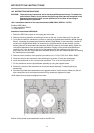
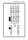
4. Remove the two resistors of the specific input channel (IN 1: R104 / R105, IN 2: R204 / R205).
5. Clean the holes for the transformer from soldering tin by suction (7 holes per transformer).
6. Insert the transformer for IN 1 into the holes at position T101 or for IN 2 at position T201.
7. Fix the transformer onto the printed board assembly by using the supplied screw.
8. Solder the contacts of the transformer on the printed board assembly (7 soldering points per
transformer).
9. Re-install all printed board assemblies in the opposite manner of their removal. Make sure that all
wire connections are re-connected and that all fixing screws are tightened in place.
10.Re-attach the cover plate and tighten its screws.
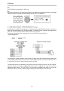
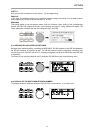
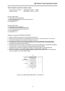
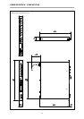
Position of the printed board assemblies inside of the DSP 244
RETROFITTING INSTRUCTIONS
10-5