


10.3.2 Installation manuals for interface cards:
Contact Closure Interface (NRS 90246, EDP-No. 112766)
RS-485 Interface (NRS 90247, EDP-No. 112767)
Contents NRS 90246:
1 x Information sheet NRS 90246
1 x Printed board assembly Contact Closure (83114)
1 x Rear plate blinding
4 x Screws M3 x 6
Contents NRS 90247:
1 x Information sheet NRS 90247
1 x Information sheet “Important Information”
1 x Printed board assembly RS-485 (83115)
1 x Rear plate blinding
4 x Screws M3 x 6
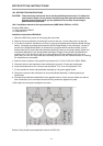
Installation instructions NRS 90246, NRS 90247:
1. Switch the DSP 244’s power off and unplug the mains cord.
2. Remove the cover plate after unscrewing 2 screws on the top, 4 on the sides, and 3 on the rear.
3. Loosen the blinding on the rear plate (2 screws on the rear).
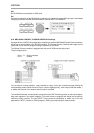
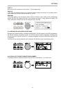
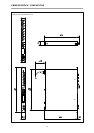
4. Install the extension kit’s printed board assembly at the correct destination (see figure below).
5. First, tighten the screws at the rear plate (A) and then the two screws that fix the printed board
assembly in place at the bottom plate (B).
6. Using the 26-pole flat wire cable (C), establish the connections between the printed board assembly
of the extension kit and the Analog Board (printed board assembly 80448).
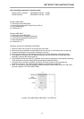
7. Re-attach the cover plate and tighten its screws. Re-insert the mains cord and switch the
appliance’s power on. The newly installed interface is automatically recognized.
8. Now, you are able to make all necessary software settings for the interface in the OPTION mode
(see also chapter 9, OPTION FUNCTIONS).
Position of the NRS 90246, NRS 90247 in the DSP 244
RETROFITTING INSTRUCTIONS
10-6