Cresnet 4-Channel Digital Volume Control Crestron C2N-VEQ4
6 • Cresnet 4-Channel Digital Volume Control: C2N-VEQ4 Operations Guide - DOC. 6135A
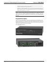
balanced/unbalanced output (OUT) ports to an amplifier. Each channel includes a
muting relay with 100 dB attenuation.
G (Chassis Ground)
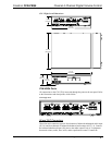
Use this chassis screw to ground the unit to the amplifier and audio source common
grounds.
NET
This 4-pin network connector is used to connect the C2N-VEQ4 module to the
Cresnet system. Data and power for the C2N-VEQ4 are provided via the connection.
Refer to “Network Wiring” on page 7.
C2N-VEQ4 Indicators
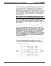
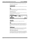
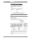
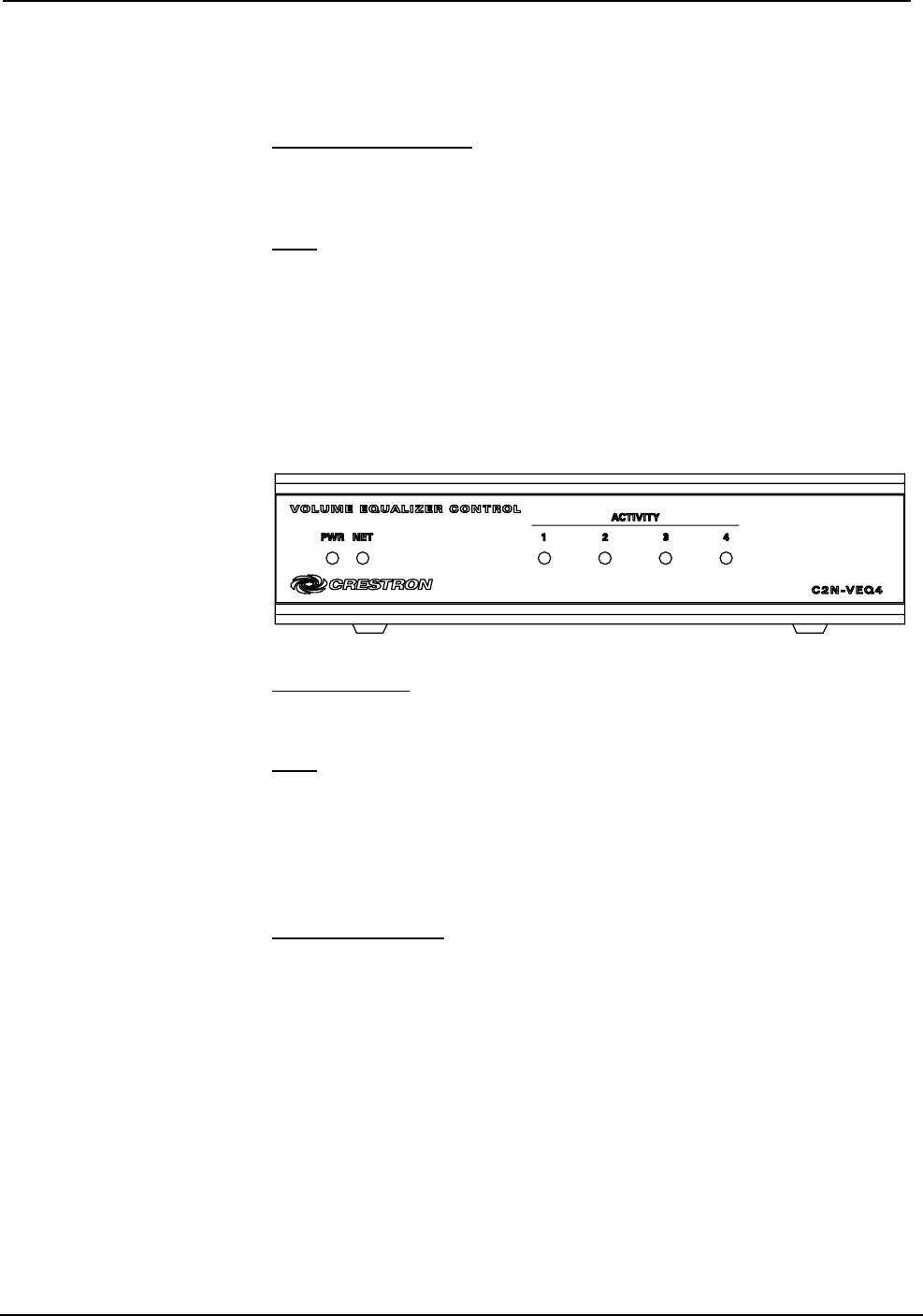
There are six LED indicators located on the front panel of the C2N-VEQ4. Refer to
the illustration below and descriptions that follow.
C2N-VEQ4 Indicators
PWR (Power)
This green LED illuminates when power is supplied to the C2N-VEQ4.
NET
This yellow LED illuminates when communication between the control system and
the C2N-VEQ4 is established (the unit is polled on the network). Illumination
indicates that the program currently loaded has a network device defined at the same
ID as the C2N-VEQ4. The LED flashes when communication with the processor
occurs.
ACTIVITY (1 – 4)
These red LEDs illuminate only when there is activity on any of the four channels.
Activity includes any change in volume, tone (bass, treble), mixer, or equalization
parameters. Once the command is completed, the related LED(s) go out.
SETUP LED and Pushbutton
The C2N-VEQ4 is TSID ready. The SETUP pushbutton and its associated LED are
located on the rear panel and are used for setup of the unit’s network ID during the
initial configuration of a Cresnet
®
system or when the device is being added/replaced.
Refer to “Method B (Touch Settable IDs)” on page 9 for detailed information.


