


CTL/EXP
32
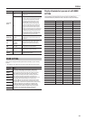
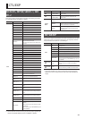
ASSIGN COMMON
Parameter Value Explanation
INPUT SENS 0–100
This adjusts the input sensitivity when INPUT
LEVEL is selected for SOURCE.
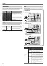
ASSIGN 1–8
* If you want to light the ACCEL/CTL pedal’s LED indicator while the
ASSIGN 1–8 function is assigned to the ACCEL/CTL pedal, set the ACCEL/
CTL pedal FUNC (p. 31) to “LED ON/OFF.”
Parameter Value Explanation
OFF/ON OFF, ON Turns the ASSIGN 1–8 on/o.
SOURCE
EXP PEDAL Assigns the GT-100’s [EXP] pedal.
EXP PDL SW Assigns the EXP pedal switch.
P.LOOP PEDAL Assigns the GT-100’s [PHRASE LOOP] pedal.
ACC/CTL PDL Assigns the [ACCEL/CTL] pedal.
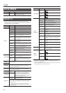
SUB EXP PDL
Assigns the external expression pedal (such as
the separately available EV-5) connected to the
SUB CTL 1, 2/SUB EXP jack.
SUB CTL1 PDL
Assigns the external footswitch (FS-5U, FS-6;
available separately) connected to the SUB CTL
1, 2/SUB EXP jack.
SUB CTL2 PDL
Assigns the external foot switch (FS-5U, FS-6;
available separately) connected to the SUB CTL
1, 2/SUB EXP jack.
INT PEDAL
Refer to “Virtual expression pedal system
(Internal Pedal / Wave Pedal)” (p. 35)
WAVE PEDAL
Refer to “Virtual expression pedal system
(Internal Pedal / Wave Pedal)” (p. 35)
INPUT LEVEL
The assigned target parameter will change
according to the input level.
CC#1–#31
Control Change messages from an external MIDI
device.
CC#64–#95
Control Change messages from an external MIDI
device.
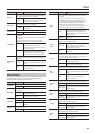
SOURCE MODE
MOMENT
The normal state is O (minimum value), with
the switch On (maximum value) only while the
footswitch is depressed.
TOGGLE
The setting is toggled On (maximum value)
or O (minimum value) with each press of the
footswitch.
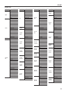
TARGET
CATEGRY
This selects the parameter to be changed.
Refer to TARGET list
TARGET
TARGET MIN
This sets the minimum value for the range in which the parameter
can change. The value diers depending on the parameter
assigned for TARGET parameter.
TARGET MAX
This sets the maximum value for the range in which the parameter
can change. The value diers depending on the parameter
assigned for TARGET parameter.
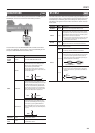
ACT RANGE LO 0–126
You can set the controllable range for target
parameters within the source’s operational
range. Target parameters are controlled within
the range set with ACT RANGE LO and ACT
RANGE HI. You should normally set ACT RANGE
LO to 0 and ACT RANGE HI to 127.
ACT RANGE HI 1–127
WAVE RATE *1
0–100,
BPM
–
This determines the time spend for one cycle of
the assumed EXP Pedal.
When set to BPM, the value of each parameter will be set accord-
ing to the value of the “MASTER BPM” specied for each patch. This
makes it easier to achieve eect sound settings that match the
tempo of the song.
* If, due to the tempo, the time is longer than the range of
allowable settings, it is then synchronized to a period either 1/2
or 1/4 of that time.
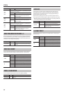
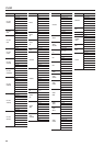
Parameter Value Explanation
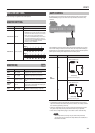
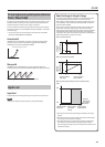
WAVEFORM *1
SAW
TRI
SINE
INT PDL
TRIGGER *2
PATCH CHANGE This is activated when a patch is selected.
EXP PDL-LO
This is activated when the GT-100’s [EXP] pedal is
set to the minimum position.
EXP PDL-MID
This is activated when the GT-100’s [EXP] pedal is
moved through the middle position.
EXP PDL-HI
This is activated when the GT-100’s [EXP] pedal is
set to the maximum position.
EXP PDL SW
This is activated when the EXP pedal switch is
operated.
P.LOOP PEDAL
This is activated when the [PHRASE LOOP] pedal
is operated.
ACC/CTL PDL
This is activated when the [ACCEL/CTL] Pedal is
operated.
SUB EXP PDL
This is activated when an external expression
pedal connected to the SUB CTL 1, 2/SUB EXP
jack is operated.
SUB CTL1 PDL
This is activated when an external footswitch
connected to the SUB CTL 1, 2/SUB EXP jack is
operated.
SUB CTL2 PDL
This is activated when an external footswitch
connected to the SUB CTL 1, 2/SUB EXP jack is
operated.
CC#1–#31
This is activated when a control change is
received.
CC#64–#95
This is activated when a control change is
received.
INT PDL TIME
*2
0–100
This species the time over which the internal
pedal will move from the toe-raised position to
the toe-down position.
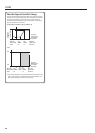
INT PDL
CURVE *2
LINEAR
SLOW RISE
FAST RISE
*1 The WAVE RATE and WAVEFORM parameters are enabled when the Source
parameter is set to WAVE PEDAL.
*2 The INT PDL TRIGGER, INT PDL TIME, and INT PDL CURVE parameters are enabled
when the SOURCE parameter is set to INT PEDAL.