


SYSTEM
29
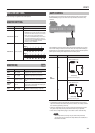
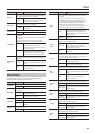
Parameter Value Explanation
MIX LEVEL
Adjusts the level of the audio input from the computer that
will be mixed with the sound processed by the GT-100’s eects
when “USB IN-OUT MODE” is not set to “REAMP”.
0–200 %
Adjusts the level of the audio input from the
computer that will be mixed with the sound
processed by the GT-100’s eects.
INPUT LEVEL
Adjusts the input level from the computer to the GT-100’s eects
when “USB IN-OUT MODE” is set to “REAMP”.
-20–+20 dB
Adjusts the input level from the computer to the
GT-100’s eects .
OUTPUT LEVEL
Adjusts the level of the output from the GT-100 to the computer.
0–200% Adjusts the level of the output to the computer.
DIR. MONITOR
Switches the output of the GT-100 sound to the OUTPUT and
PHONES jacks.
* This setting cannot be saved. It is set to ON when the power
is turned on.
* If you are using the special driver, you can control DIR.
MONITOR On/O from ASIO 2.0 - compatible application.
OFF
Set this to O if transmitting audio data
internally through a computer (Thru).
No sound is heard at this time unless the setting
for the computer is Thru.
ON
The GT-100 sound is output. Set this to ON
when using the GT-100 as a standalone device,
without connecting to a computer (only USB
input sound will be output if this is set to O).
DIR. MONITOR
CMD
This setting determines whether or not the command (the
Direct Monitor command) controlling the Direct Monitor setting
is enabled.
DISABLE
The Direct Monitor command is disabled,
maintaining the Direct Monitor mode set by the
GT-100.
ENABLE
The Direct Monitor command is enabled, allow-
ing the Direct Monitor mode to be switched
from an external device.
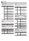
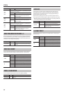
MIDI SETTING
Here you can make settings for using the GT-100 connected with an
external MIDI device or with a second GT-100 unit.
Parameter Value Explanation
RX CHANNEL
This sets the MIDI channel used for receiving MIDI messages.
Ch. 1– Ch. 16 Species the receive channel.
OMNI MODE
This makes the settings for the channels used for MIDI
information.
OFF
Information is received on the channel specied
by the RX CHANNEL setting.
ON
Messages are received on all channels, regard-
less of the MIDI channel settings.
TX CHANNEL
This sets the MIDI channel used for transmitting MIDI messages.
Ch. 1– Ch. 16. Species the transmit channel.
RX
Transmits on the same channel as the RX
CHANNEL.
DEVICE ID
This sets the MIDI Device ID used for transmitting and receiving
Exclusive messages.
1–32 Sets the MIDI Device ID.
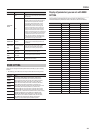
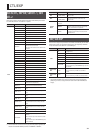
Parameter Value Explanation
SYNC
CLOCK
This setting determines the basis used for synchronizing
the timing for eect modulation rates and other time-based
parameters.
* When you have an external MIDI device connected, the
MASTER BPM is then synchronized to the external MIDI
device’s tempo, thus disabling the MASTER BPM setting. To
enable setting of the MASTER BPM, set to “INTERNAL.”
* When synchronizing performances to the MIDI Clock
signal from an external MIDI device, timing problems in the
performance may occur due to errors in the MIDI Clock.
AUTO
Operations are synchronized to the MIDI Clock
received via MIDI. However, operations are
automatically synchronized to the GT-100’s
internal Clock if the GT-100 is unable to receive
the external Clock.
INTERNAL
Operations are synchronized to the GT-100’s
internal Clock.
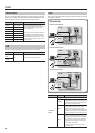
MIDI IN
SELECT
This selects whether MIDI messages will be received from the
MIDI IN connector or from the USB port.
USB (AUTO)
MIDI messages will be received via the USB port.
* If the USB port is not connected to a
computer, MIDI messages will be received
from the MIDI IN connector.
MIDI
MIDI messages will be received from the MIDI
IN connector.
PC OUT
This setting determines whether or not Program Change
messages are output when patches are switched on the GT-100.
* On the GT-100, Bank Select messages are output simultane-
ously with Program Change messages.
OFF
Program Change messages are not output, even
when patches are switched.
ON
Program Change messages are simultaneously
output when patches are switched.
MAP
SELECT
This setting determines whether patches are switched according
to the Program Change Map settings, or to the default settings.
FIX
This deactivates the Program Change Map.
Switches to the patches according to the default
settings.
PROG
This activates the Program Change Map.
Switches to the patches according to the
Program Change Map.
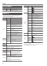
PH.LOOP
OUT
This sets the controller number when [PHRASE LOOP] pedal
switch operation data is output as Control Change messages.
OFF Control Change messages are not output.
CC#1–CC#31,
CC#64–CC#95
This sets the controller number when [PHRASE
LOOP] pedal operation data is output as Control
Change messages.
ACC/CTL
OUT
This sets the controller number when [ACCEL/CTL] pedal switch
operation data is output as Control Change messages.
OFF Control Change messages are not output.
CC#1–CC#31,
CC#64–CC#95
This sets the controller number when [ACCEL/
CTL] pedal operation data is output as Control
Change messages.
EXP OUT
This sets the controller number when [EXP] pedal operation data
is output as Control Change messages.
OFF Control Change messages are not output.
CC#1–CC#31,
CC#64–CC#95
This sets the controller number when [EXP]
pedal operation data is output as Control
Change messages.
EXP SW
OUT
This sets the controller number when EXP PEDAL SW operation
data is output as Control Change messages.
OFF Control Change messages are not output.
CC#1–CC#31,
CC#64–CC#95
This sets the controller number when EXP
PEDAL SW operation data is output as Control
Change messages.