


Page 34 User Guide English
User Guide pro.Bose.com
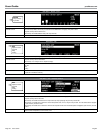
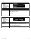
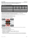
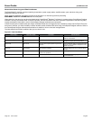
Sample Output Configurations for Different Loudspeaker Loads
This table should help you select the appropriate output mode for a given loudspeaker load.
Figure 14. Loudspeaker load output configurations
Power Rating (20 - 20 kHz) 2 Ω 4 Ω 8 Ω 70 V 100 V
THD For Power Rating <0.1% THD 1% THD
Mono Mode: 8 channels (per channel) 500 W 500 W 300 W not available not available
V-Bridge Mode: 4 channels (per channel) 500 W
(1)
1000 W 1000 W 800 W 1000 W
I-Share Mode: 4 channels (per channel) 1000 W 500 W
(1)
300 W
(1)
not available not available
Quad Mode: 2 channels (per channel) 1000 W
(1)
2000 W 1000 W
(1)
1600 W 2000 W
Maximum Rated Power, Total All Channels 4000 W
Peak Output Voltage (Mono/V-Bridge/Quad modes) 71 / 142 / 142 V
Voltage Gain (Mono/V-bridge/I-Share/Quad modes) 33 / 36 / 33 / 36 dB
Notes for Power Ratings
(1)
Configuration not optimal/not recommended
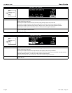
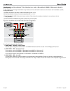
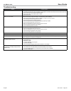
For reference, the following two examples illustrate two different output configurations using RoomMatch™ array module loudspeakers.
Front panel configuration settings are provided. While not covered in this documentation, ControlSpace
®
Designer™ software provides
additional configurability to these examples. Further information on this software can be found on pro.Bose.com.
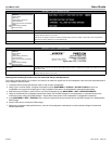
Configuration of a RoomMatch
™
Four-Module Array (Example 1)
In this example, four full-range RoomMatch array modules are connected to one PowerMatch™ amplifier, arranged as follows:
(2) Bose® RoomMatch 7010 array module loudspeakers (70° H x 10° V)
(2) Bose RoomMatch 12020 array module loudspeakers (120° H x 20° V)
(1) Bose PowerMatch PM8500 configurable professional power amplifier
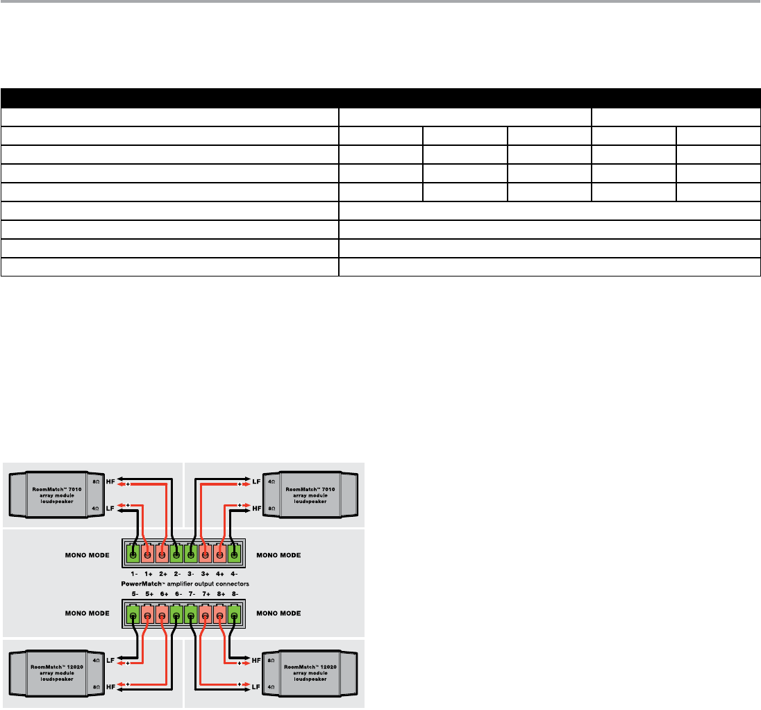
Figure 15. RoomMatch four-module array configuration
Note: All RoomMatch loudspeaker connections use Neutrik NL4 speakON-type cable connectors. Please refer to RoomMatch
loudspeaker documentation for further details.
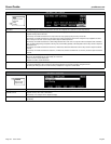
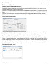
Front Panel Configuration Menu Settings:
1. MAIN MENU < CONFIG < OUTPUT CONFIG
Set the output configuration for channels 1-8 to MONO mode.
2. MAIN MENU < DSP < SPEAKER PRESETS
For channels 1, 3, 5, and 7 set SERIES to “RoomMatch” and MODEL to “RM_Array LF.”
For channels 2, 4, 6, and 8 set SERIES to “RoomMatch” and MODEL to “RM_Array HF.”
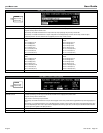
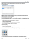
3. MAIN MENU < DSP < ARRAY EQ
For each input channel (A-H) that is routed to an output channel, set the MODULES value to 4 and the V-Angle parameter to
60 degrees, which is the total vertical angle of the four shown modules. Ensure that the state of the Array EQ is toggled to ON.