


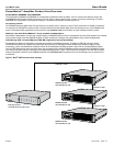

English User Guide Page 17
pro.Bose.com User Guide
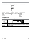
Wiring Input Connectors
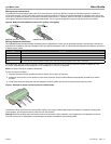
The balanced line-level analog inputs utilize 3-pin terminal block connectors (Phoenix Contact #1776168, supplied). For balanced
inputs, strip the wire ¼ inch (6 mm) and connect the respective positive, negative, and ground terminals as indicated on the unit and in
Figure 6. For unbalanced inputs, the connector should be wired with Pin 1 = positive, with Pin 2 and Pin 3 connected with a jumper wire
(not supplied) and then connected to the input cable shield. You can use the supplied tie wraps to help secure the input cables.
Figure 6. Balanced and unbalanced connectors (jumper not supplied)
Balancedconnector Unbalancedconnector
Wiring Output Connectors
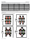
The PM8500 features flexible software-selectable output configurations. Power can be allocated between 2 and 8 output channels for
specified low-impedance and high-impedance (70V and 100V) loudspeaker loads. The following table describes the behavior of the four
available output modes.
Mode Description
Mono Each channel operates independently, and will drive 2 to 16 Ohm loads
V-Bridge Channel pairs are combined to deliver 2x voltage and will drive high impedance (70V or 100V) and 4 to 16 Ohm loads
I-Share Channel pairs are combined to deliver 2x current, and will drive 2 Ohm loads
Quad Two channel pairs are combined to deliver 2x voltage and 2x current while driving high impedance (70V or 100V) or 4 Ohm loads
The loudspeaker outputs utilize two (2) high-current, 8-pin locking terminal block connectors (Phoenix Contact COMBICON
®
Part
#1778120, supplied) that accept cables from 10 to 24 AWG (5.3 - 0.2 mm
2
) in diameter.
Note: Use Class 2 wiring for speaker connections.
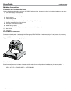
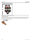
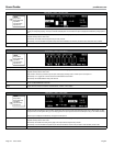
To wire the output connector:
1. Strip the insulation off each speaker terminal to expose 10 mm (3/8") of bare wire.
2. Insert each wire into the correct position on the block connector. Use a small flat-blade (or appropriate) screwdriver to secure
the wire.
3. Firmly press the block connector into the receptacle on the amplifier until the left and right latches snap into place.
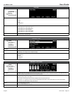
Figure 7. Example of output connector wired for I-Share mode
1+
2+
1-
2-
To detach the block connector from the amplifier, slide the two orange release tabs toward the amplifier to release the locking tabs.
Once released, pull the terminal block connector from the amplifier.
Warning: While the amplifier does self-protect under most improper output conditions, misconfiguration of loudspeaker mode and
incorrect connection of loudspeakers could damage connected loudspeakers and/or the amplifier.