


Page 14 User Guide English
User Guide pro.Bose.com
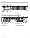
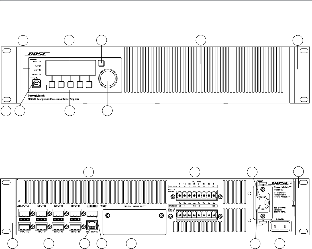
Controls, Display, and Connectors
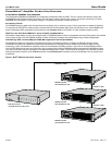
Figures 2 and 3 detail the various elements found on the front and rear panels of the PM8500 and PM8500N amplifiers.
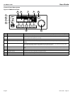
Figure 2. PM8500 and PM8500N Front Panel View
1. LED Indicators
2. LCD
3. Navigation Soft Key
4. Rotary Encoder
5. Menu Soft Keys (1-5)
6. USB connector
7. Front airflow vents
8. Front rack-mount ears
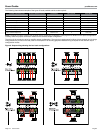
Figure 3. PM8500N Rear Panel View (PM8500 identical except no RJ-45 network connector)
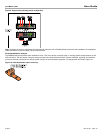
9. Analog Input connectors (A-H)
10. Fault-Notification Output
11. Ethernet RJ-45 network connector (PM8500N only)
12. Rear airflow vents
13. Digital input card slot cover
14. Output connectors (1-4 and 5-8)
15. AC Mains receptacle
16. AC Mains retention clip
17. Power Switch/Resettable Circuit Breaker
18. Rear rack-mount support tabs
3
1
2
456
7
8
8
9
14
11
12
15
17131018
18
16