


Page 18 User Guide English
User Guide pro.Bose.com
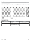
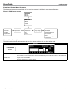
The following chart shows examples of the types of loads possible and the mode required:
Intended Loudspeaker Load Number of Affected Channels Power Rating Max Channels Output Mode
2 to 16 Ohms 1 500 W @ 4Ω 8 Mono
4 to 8 Ohms 2 1000 W @ 8Ω 4 V-Bridge (Low-Z)
70-V “constant voltage” lines 2 800 W @ 70V 4 V-Bridge (70V)
100-V “constant voltage” lines 2 1000 W @ 100V 4 V-Bridge (100V)
2 Ohms requiring high current 2 1000 W @ 2Ω 4 I-Share (Low-Z)
4 Ohms requiring high power 4 2000 W @ 4Ω 2 Quad (Low-Z)
70-V “constant voltage” lines 4 1600 W @ 70V 2 Quad (70V)
100-V “constant voltage” lines 4 2000 W @ 70V 2 Quad (100V)
Note: Configure the output mode of the amplifier before connecting loudspeakers. See page 24 for details on front panel configuration.
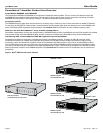
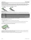
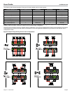
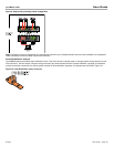
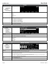
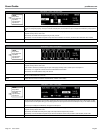
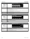
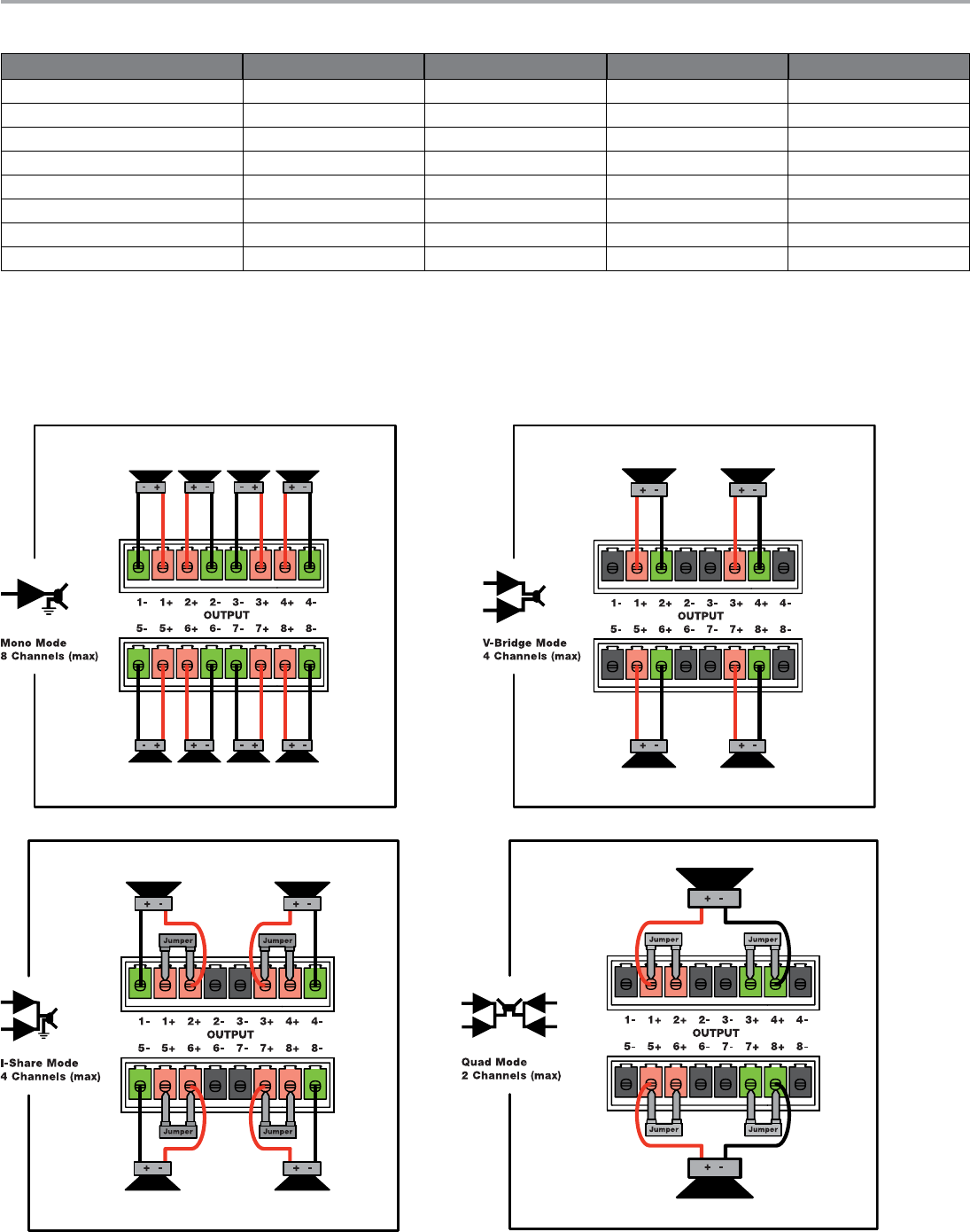
Carefully follow the proper connection method for the selected output configuration.
The wiring of the connector varies by amplifier output configuration. The output pin assignments for Mono (single channel) and V-bridge
configurations are printed on the rear panel of the amplifier. The following graphics illustrate wiring examples for the different output
configuration modes.
Figure 8. Output wiring showing the four basic configurations