


English User Guide Page 19
pro.Bose.com User Guide
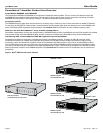
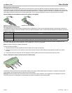
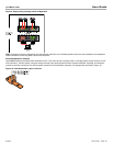
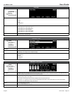
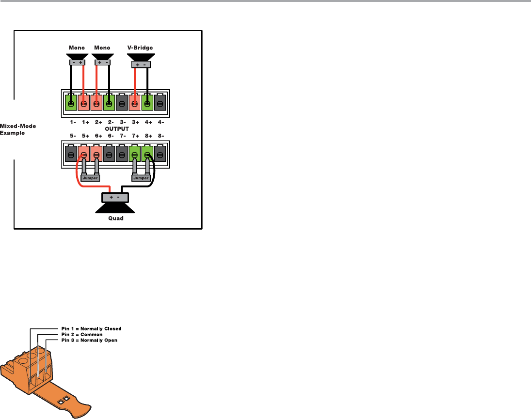
Figure 9. Output wiring showing mixed configuration
Note: Changing the output configuration will automatically place the unit in Standby Mode to allow the safe installation of loudspeaker
cable connections to the rear-panel output terminal blocks.
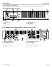
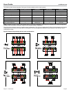
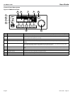
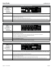
Fault Notification Output
The PM8500 features a hardware fault notification circuit. This circuit drives a normally open or normally closed contact closure (1A, 30
VDC maximum). The fault output, using the orange-colored 3-pin terminal block (Phoenix Contact #1976010, supplied), is intended to
provide an external connection to a remote system monitor for fault notification purposes. Pin assignments are noted in Figure 10.
Figure 10. Fault Notification output connector