


English User Guide Page 21
pro.Bose.com User Guide
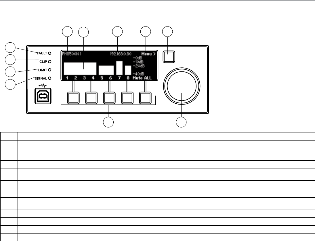
Control Panel Description
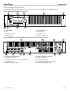
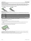
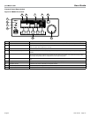
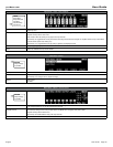
Figure 12. PM8500 Front Panel
1 Fault LED Indicator LED lights red when a fault condition has been detected. For more information see Figure 21, “Fault Conditions” on page 38.
2 Clip LED Indicator Indicates red when the input signal reaches full scale. Bose recommends that you reduce input levels to prevent this condition.
3 Limit LED Indicator When this LED illuminates, indicates that one or more output channels have reached user-adjustable RMS or Peak threshold
values or if system internal protection is occurring.
4 Signal LED Indicator Flashes with the presence of input signal.
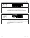
5 Hardware Name / Menu Depth Displays the name (either default or assigned) given to this amplifier. This can be changed using ControlSpace
®
Designer™
software.
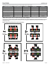
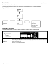
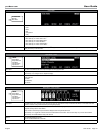
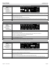
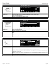
6 Meters While at the operating screen (shown), each channel shows the status and level of its output. Muted channels show MUTE in
the bar and lumped channel modes show grouped bars as shown above with channels 1-4 and channels 5-6. Output meters
automatically change display width to correspond to the active output configuration.
7 IP Address / Device ID Shows the IP address (PM8500N) or device ID number (PM8500). Setting can be modified using ControlSpace Designer soft-
ware.
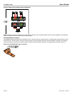
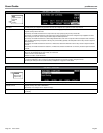
8 Navigation Indicator Indicates which menu level will be actuated when the Navigation Soft Key is pressed.
9 Navigation Soft Key Actuates the menu level as indicated by the Navigation Indicator.
10 Menu Soft Keys (1-5) Selects various options that appear on the LCD screen directly above these controls.
11 Rotary Encoder This spin/press control wheel allows scrolling and selection of items shown in lists.
1
11
5 6 7 8 9
10
2
3
4