


PAGE
25
Community XLT / XLTE Series Owner’s Manual
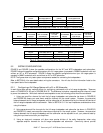
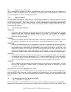
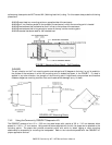
7.3.1 Model 41 Horn Orientation
The 41 is shipped from the factory for monitor use meaning that when in a horizontal position its HF pattern is 90
degrees horizontal by 40 degrees vertical. For operating it in an upright position as a PA loudspeaker, rotate the horn
so its coverage pattern will remain at 90 degrees horizontal.
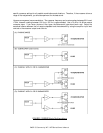
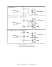
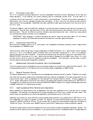
7.3.2 Model 42 and 46
For these models, one reason for rotating the horn is for operating the speaker in a horizontal position so that the
coverage pattern will be wide horizontally. Another is for operating in the normal upright position so the coverage
will be narrow horizontally. This is useful when two or more loudspeakers are arrayed and splayed because it
reduces coverage pattern overlap. This helps reduce high frequency acoustic interaction between them (comb
filtering and level variations).
7.4 MOUNTING AND RIGGING
WARNING:
Mounting or rigging loudspeakers is a serious endeavor and requires an experienced professional. Improper
installations may result in equipment damage, personal injury, or death. For this reason, no loudspeaker
should be mounted or suspended overhead unless the method has been approved by a registered
Professional Structural Engineer.
DANGER:
Under no circumstances should the handles be used for mounting or suspending the loudspeaker. They are
not designed for this purpose and such use may result in equipment damage, personal injury, or death.
WARNING:
Under no circumstances should an XLT loudspeaker be mounted or suspended overhead when exposed in
the out-of-doors, or in high humidity conditions using the T-nut mounting points on the loudspeaker. The
wood material used to manufacture the loudspeakers, while strong and durable for normal use, is not
impervious to moisture. For this reason, the T-nut mounting points could fail after a period of time if the
enclosure is exposed to high moisture intermittently or continuously. If it is to be mounted in such
conditions an alternate method must be used and approved by a registered Professional Structural Engineer.
CAUTION:
All fixed hardware used for overhead mounting or suspension should be designed, tested, and/or certified for
its intended use with a minimum design factor of 5:1. A minimum design factor of 8:1 should be used for
any component subject to movement, continuous wear, or friction, such as moving wire rope. The design
factor is the ratio between the structural failure point and the load to be applied to the component.
CAUTION:
Routine inspections and maintenance should be performed on any mounting or rigging system. Any parts
found to have deterioration, excessive fatigue, or excessive wear should be removed from service
immediately and replaced.
IMPORTANT NOTE: Mounting/Rigging Point Holes
All mounting/rigging points, T-nut mounting points, and stand adapter points for all XLT and XLTE loudspeakers must
either be used for mounting hardware or remain plugged with the supplied screws. If they are not plugged up, these
points can create air leaks in the enclosure that will compromise the LF performance with reduced output and/or
distortion.
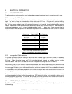
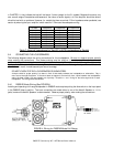
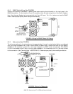
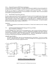
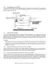
7.4.1 XLT Mounting Points (XLT Series and XLT48E)
(Refer to FIGURE 7 and FIGURE 8)
All XLT loudspeakers and the XLT48E have internal, captive, 5/16-18 threaded inserts (T-nuts) for suspension or
permanent mounting located on the enclosure top, sides and bottom (sides only for the XLT48 and XLT48E). While