


PAGE
10
Community XLT / XLTE Series Owner’s Manual
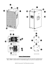
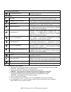
OTHER MOUNTING POINTS
GRILLE MOUNTING POINTS
The grille is fastened to the enclosure with
1-1/2 in. / 38 mm #6
Phillips pan-head
screws.
INPUT PANELS
INPUT PANEL
For connecting the power amplifier to the loudspeaker. Also has
user adjustable controls and PowerSense protection indicator.
POWERSENSE
™
DDP
4
INDICATOR
This LED indicator lights red whenever the PowerSense DDP
circuitry operates. It indicates the loudspeaker is being overdriven.
HF LEVEL SWITCH
A 2-position switch used to adjust the volume level of the high
frequencies for more (+4 dB) or less (FLAT) output.
PASSIVE / BIAMP SWITCH
Used to select the loudspeaker’s operating mode. Down position
is for PASSIVE mode (single amplifier) and up position is for BIAMP
mode (separate LF and HF amplifiers).
NEUTRIK SPEAKONS
5
Signal Input: 4 terminal NL4MP jacks. Accept NL4FC in-line
connectors. Used for both PASSIVE and BIAMP modes. Use
terminals #1 +/- for PASSIVE mode or for BIAMP LF input. Use
terminals #2 +/- for BIAMP HF input (not used for PASSIVE
mode). The two jacks are in parallel.
6
11
DUAL 1/4 in. PHONE JACKS
5
Signal Input. Accepts 1/4 in. tip/sleeve (2 conductor) phone plug.
Tip = +, Sleeve = -. Use either jack for PASSIVE mode. Not used
for BIAMP mode. The two jacks are in parallel.
6
12
NEUTRIK SPEAKONS
5
Subwoofer signal input. Neutrik NL4MP jacks accept NL4FC in-
line connectors. Use terminals #1 +/-. Terminals #2 +/- are not
used. The 2 jacks are in parallel and in parallel with 1/4 in. jacks
.
6
13
DUAL 1/4 in. PHONE JACKS
5
Subwoofer signal input. Accepts 1/4 in. tip/sleeve (2 conductor)
phone plug. Tip = +, Sleeve = -. The two jacks are in parallel
and in parallel with the Neutrik jacks.
6
1/4 in. PHONE JACK – HIGH PASS OUTPUT
High-pass output (150 Hz and above) for connecting a full-range
loudspeaker when using a single amplifier to power both the
subwoofer and full-range loudspeaker.
OTHER FEATURES
HANDLES
Use only for carrying and handling - DO NOT USE for mounting or
suspending the enclosure.
PROTECTIVE CORNERS
Protect the corners from damage, act as feet when the enclosure is
freestanding, and mesh with corners on other enclosures when
stacking so as to position and help stabilize the enclosure on top.
FEET
Heavy-duty rubber feet. Installed by user on the XLT41E.
LOGO
Community logo recessed into grille.
Footnotes for Physical Features
1 Use ONLY for a horizontal pull direction, i.e. parallel to the enclosure surface where the insert is located.
CAUTION
:
Refer to SECTION 7.4 for further information.
2 These points are ONLY for supporting the loudspeaker from the bottom.
DANGER
:
These points are not intended nor load rated for suspending the loudspeaker.
3 Vertical pull is perpendicular to the enclosure surface where the rigging point is located.
Horizontal pull is parallel to the enclosure surface where the rigging point is located.
CAUTION
:
Refer to SECTION 7.5 for further information.
4 DDP = Dynamic Driver Protection
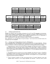
5 Use either type of input jack - Neutrik or 1/4 in. Refer to SECTION 6.2 for further information.
6 An unused Neutrik or 1/4 in. jack can be used as a signal output for paralleling to a 2nd loudspeaker.
Refer to SECTION 6.3 for further information.