


PAGE
17
Community XLT / XLTE Series Owner’s Manual
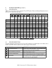
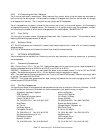
MODEL
LOUDSPEAKER
PROGRAM RATING
REC. POWER AMP
RANGE
POWER AMP
LOAD IMPEDANCE
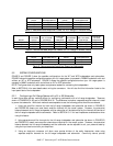
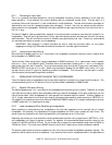
41, 42, 43, and 48 500W 420W to 600W 8 Ohm
46 500W 420W to 600W 4 Ohm
47 1000W 830W to 1200W 4 Ohm
Table 3: Recommended Amplifier Power for Full-Range in PASSIVE Mode
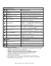
MODEL
LF PROGRAM
RATING
REC. LF POWER
AMP RANGE
POWER AMP
LF LOAD
IMPEDANCE
HF PROGRAM
RATING
REC. HF POWER
AMP RANGE
POWER AMP
HF LOAD
IMPEDANCE
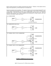
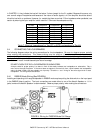
41, 42, 43, and 48 500W 420W to 600W 8 Ohm 125W 100W to 150W 8 Ohm
46 500W 420W to 600W 4 Ohm 200W 150W to 250W 8 Ohm
47 1000W 830W to 1200W 4 Ohm 125W 100W to 150W 8 Ohm
Table 4: Recommended Amplifier Power for Full-Range in BIAMP Mode
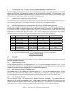
MODEL
SUBWOOFER
PROGRAM RATING
REC. POWER AMP
RANGE
POWER AMP
LOAD IMPEDANCE
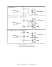
51 300W 240W to 360W 8 Ohm
55 750W 630W to 900W 4 Ohm
Table 5: Recommended Amplifier Power for Subwoofer
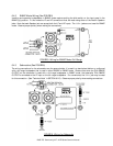
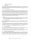
5.2 SYSTEM CONFIGURATIONS
FIGURE 2 and FIGURE 3 show the possible configurations for the XLT and XLTE loudspeakers and subwoofers.
FIGURE 2 shows the possible configurations when your full-range system is operated in PASSIVE mode both with and
without an XLT or XLTE subwoofer. FIGURE 3 shows the possible configurations when your full-range system is
operated in BIAMP mode both with and without an XLT or XLTE subwoofer.
NOTE: The figures show only basic system components needed for connecting the loudspeakers.
Refer to SECTION 6.4 for exact details about wiring the connectors. You will also find this information listed on the
input panel label of the loudspeaker.
5.2.1 Configuring a Full-Range System with a 51 or 55 Subwoofer
In each figure there are two methods shown for configuring a subwoofer with a full-range loudspeaker. These are
shown in FIGURES 2C & 2D and in FIGURES 3B & 3C. The difference is whether a separate amplifier channel is used
to power the subwoofer. While both methods are acceptable to use, the following points should be considered.
1.
Using one amplifier channel
for both the full-range loudspeaker and subwoofer (as shown in FIGURE 2C
and FIGURE 3B) means you need fewer amplifier channels for the overall system. However, the acoustical
balance between the full-range loudspeaker and the subwoofer will be determined by the inherent efficiencies of
the full-range loudspeaker and the subwoofer. Refer to SECTION 5.1.2 for load impedance considerations when
using this feature.
2.
Using separate amplifier channels
for the full-range loudspeaker and subwoofer (as shown in FIGURE 2D
and FIGURE 3C) means more amplifier channels are required for the overall system. However, the acoustical
balance between the full-range loudspeaker and the subwoofer can be adjusted to suit your personal taste by
using the input level controls on your amplifiers.
3.
Using an electronic crossover
will allow more precise division of the audio frequencies, when using
separate amplifier channels for the full-range loudspeaker and subwoofer. Community cannot provide