


PAGE
9
Community XLT / XLTE Series Owner’s Manual
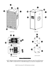
3PHYSICAL FEATURES
(See FIGURE 1)
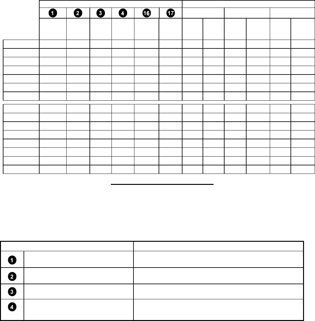
3.1 FEATURES MATRIX
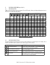
TABLE 1 lists various features that vary between XLT and XLTE models. Refer to the Features Descriptions chart in
SECTION 3.2 for details about each feature.
PHYSICAL FEATURES ENCLOSURE
MATERIAL FINISH GRILLE STYLE
Mounting
Points
Stand
Adapter
Points
Rigging
Points
Stand
Socket
Protec-
tive
Corners Feet
OSB
Wood
13-ply
Baltic
Birch
Carpet
Finish
Paint
Finish
Flat
Grille
Beveled
Grille
XLT41
""
XLT43
""""""
XLT46
"" " " " "
XLT47
"""""
XLT48
"" " " " "
XLT51
""""""
XLT55
"""""
XLT41E
"""""
XLT42E
"" " " " "
XLT43E
"" " " " "
XLT46E
"" " " " "
XLT47E
"""""
XLT48E
"" " " " "
XLT51E
"" " " " "
XLT55E
"""""
Table 1: Physical Features Matrix
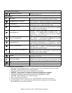
3.2 FEATURES DESCRIPTIONS
This chart describes the physical features for XLT and XLTE. Because not all features apply to all models, refer to
FIGURE 1 and TABLE 1 Matrix to determine which features apply to which products.
MOUNTING POINTS DESCRIPTION
T-NUT MOUNTING POINTS
1 each on top, 2 sides, and bottom. 5/16-18 threaded inserts.
Used for permanently mounting the loudspeaker.
1
STAND ADAPTER MOUNTING POINTS
2 on bottom. 5/16-18 threaded inserts that mate with Ultimate
Support™ stand adapter or similar.
2
MOUNTING / RIGGING POINTS
3 on top and 3 on bottom. 3/8-16 captive nuts. WLL per point =
150 lb. / 68 kg vertical pull and 60 lb. / 27.2 kg horizontal pull.
3
STAND SOCKET
1-3/8 in. / 35 mm I.D. stand / pole socket for Ultimate Support or
similar stands or poles. On XLT51 and XLT51E the socket is used
for pole mounting a full-range loudspeaker.