


PAGE
21
Community XLT / XLTE Series Owner’s Manual
6.2.1 Choosing an Input Jack
The 1/4 in. connector has been adopted for use as a loudspeaker connector primarily because of its low cost and
ready availability. It has relatively low current handling and low mechanical contact force. This can result in a
connection failure over time even if it is left undisturbed in a fixed installation. The jack and connector are subject to
deterioration over time with repeated plugging and unplugging. As such, they may not always provide optimum
signal transfer to the loudspeaker. Soldering is normally required to make a good connection from the wire to the in-
line 1/4 in. plug.
The Neutrik Speakon jacks are specifically designed to provide excellent mechanical and electrical connection for
loudspeakers. They can carry high amounts of current, have self-cleaning contacts, and securely lock with the mating
cable connector. They will provide the maximum reliability and performance over time. Community recommends
you use these connectors to connect your loudspeakers.
IMPORTANT:
After plugging in a Neutrik connector be sure to rotate the connector about 1/4 turn before
engaging the locking ring. Otherwise the electrical contacts will not make a good connection.
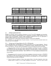
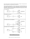
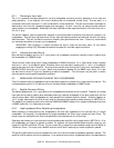
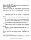
6.2.2 Internal Input Jack Wiring
Both the Neutrik Speakon and the 1/4 in. input jacks on all loudspeaker models are internally wired in parallel when
the loudspeaker is in PASSIVE mode.
Technical Note:
When using the full-range loudspeakers In BIAMP mode both 1/4 in. jacks remain wired in parallel
with pins 1+ and 1- on the Neutrik jacks. Therefore, either could be used in place of pins 1+ and 1- on the Neutrik
jacks as the input from the LF amplifier. This may be convenient when driving the LF input from a subwoofer FULL-
RANGE OUTPUT that is also a 1/4 in. jack. When using the Neutrik Speakon for the BIAMP input, either 1/4 in. jack
can also function as an LF output for paralleling a second loudspeaker. This information may be useful in certain
other situations to solve specific application problems.
6.3 PARALLELING OR DAISY-CHAINING TWO LOUDSPEAKERS
Two of the same model of loudspeakers may be connected together to operate from a single amplifier channel. This
includes paralleling the LF or HF sections of two of the same model loudspeakers in BIAMP mode.
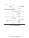
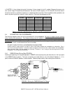
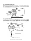
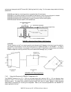
6.3.1 Parallel Connector Wiring
The Neutrik Speakon and 1/4 in. input jacks for all loudspeakers are internally wired in parallel. Therefore, an unused
input jack can be used to parallel (also called daisy-chaining) a second loudspeaker of the same model with the first
using a jumper cable. Both loudspeakers will then operate from the same amplifier channel. A Neutrik Speakon or
1/4 in. jumper cable should be wired at both ends for the appropriate operating mode according to SECTION 6.4.
The capability for paralleling functions for both the PASSIVE and BIAMP modes on full-range models except that when
in BIAMP mode the 1/4 in. jacks cannot be used.
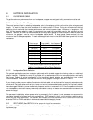
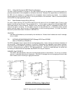
6.3.2 Load Impedance When Paralleling Loudspeakers
When paralleling or daisy-chaining two loudspeakers, the total load impedance will be one-half that of a single
loudspeaker. For example, if the impedance of a single loudspeaker is 8 Ohms, two in parallel will be 4 Ohms. The
power output for the amplifier will then be as specified by the manufacturer at a 4 Ohm load.
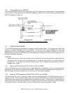
Paralleling also means you must double the recommended power amplifier rating range listed in SECTION 5.1.3 for
the loudspeakers you intend to operate in parallel. For example, the recommended power amplifier range for one
model 43 is 420W to 600W at 8 Ohms. For two model 43s in parallel the recommended range would be 840W to
1200W at 4 Ohms. This is also true in BIAMP mode for the HF and LF sections you intend to operate in parallel.
The following table lists the nominal impedance for two of the various models loudspeakers operated in parallel. The
amplifier must be rated to drive this impedance. If you examine the minimum impedances listed in the specifications