


Bulletin 639510 May 2005 10-1
Section 10
Part Numbering Scheme and Ordering Guide
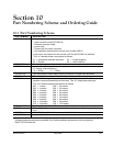
PART NUMBER DESCRIPTION
ATC200-Lite-00xx Local controller system. The system includes:
• local controller, model ATC200-Lite
• Ethernet crossover cable
• power cord*
• Phoenix 48 Volt power connector
• this installation and operation manual, part number 639510
In the future, the system will also include a CD for the ATC200-Lite software.
*The “xx” denotes power cord options as follows:
01 = Australasia (Australia and Asia) 03 = United Kingdom
02 = Europe 04 = North America
ATM200-001 Actuator
ATJB200-A01-00x Junction Box (Each junction box has 1 input, and the “x” denotes the number
of outputs as shown below.)
4 = 4-Way 7 = 7-Way
ATS-A01-002 Two-way splitter enables daisy-chaining actuators on single band antennas.
ATS-B01-003 Three-way splitter enables daisy-chaining actuators on quad port antennas.
ATCB-B01-xxx Controlcablelinkingrsttosecond,orsecondtothirdactuators.The“B”
denotes connectors assembled at both ends. The “01” designates cable type.
The “xxx” denotes cable length options as follows:
001 = 1 meter 020 = 20 meters
002 = 2 meters 030 = 30 meters
003 = 3 meters 040 = 40 meters
004 = 4 meters 050 = 50 meters
005 = 5 meters 060 = 60 meters
006 = 6 meters 070 = 70 meters
009 = 9 meters 080 = 80 meters
010 = 10 meters 090 = 90 meters
015 = 15 meters 100 = 100 meters
ATLP-200-001 Lightning Protection Unit (Recommended)
602299 Grounding Kit (Used to ground junction boxes, splitters, and lightning protection
unit.)
40417* Cable Tie Wraps (Used to secure control cable to the tower.)
68MCLICK* Hangers (Used to secure control cable to the tower.)
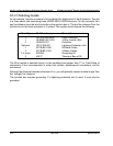
10.1 Part Numbering Scheme
*Additional cable accessories are available. See ‘Cable Installation Accessories’ link from Andrew’s
Teletilt
®
ATC200 web site.