


ATC200-Lite Teletilt
®
Remote Control Downtilt System Section 5–Device Conguration
Bulletin 639510 May 2005 5-3
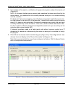
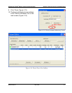
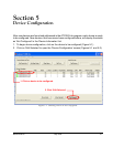
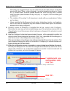
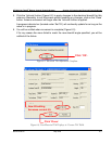
3. Click on the down arrow found on the right hand side of the ‘Antenna Model‘ drop down
list. This will display all of the available Andrew base station antenna models that were
contained in the antenna denition le that was loaded at program startup (Figure
5-2).
4. Select the desired antenna model for this actuator. Note that after an antenna model is
selected, its minimum and maximum electrical down tilt range values are displayed just
below the drop down list (Figure 5-2).
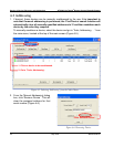
IMPORTANT: The antenna model selected *must* match the actual installed antenna
that is attached to the actuator that is being congured. Movement data specic to
this antenna will be sent to the actuator as a result of this selection. If the antenna
model selected does not match the attached antenna, the movement range sent
to the actuator will be incorrect and may prevent the antenna from functioning
correctly. See Appendix B for a reference of antenna models compatible for use with the
ATC200-Lite Teletilt
®
system. For the most current listing of antenna models designed for
use with the ATC200-Lite Teletilt
®
system, see the Base Station Antenna Teletilt
®
area of
Andrew’s web site at www.andrew.com.
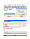
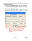
5. Use the ‘Antenna Type’ drop down list to select the antenna type that is correct for the
antenna model selected (Figure 5-2). Note that this value is used for reference only and
has no direct affect upon the Actuator/Antenna that is being congured.
6. Enter the serial number of the antenna that is attached to this actuator in the ‘Antenna
Serial #’ text entry eld. Note that this eld is optional. However, if it is entered, it must
be from 1 to 17 characters in length, and it may contain any combination of letters and
numbers (Figure 5-2).
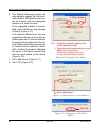
7. Using the drop down lists and entry elds, specify the parameters for the remaining elds
(Frequency Band, Technology, Base Station ID, Installer ID, Installation Date, Mechanical
Tilt, Bearing, Height, Sector, and Location). Note the following:
• A positive mechanical tilt angle means that the antenna beam is directed below the
horizontal plane. A negative mechanical tilt angle means that the antenna beam is
directed above the horizontal plane.
• The bearing is the installed compass orientation for this antenna.
• The height of the antenna on the tower must be entered in the range of 1 to 999. No
specic unit of length, such as feet or meters, is associated with this eld. However,
you should enter a value that conforms to the units of length customarily used by
your company for antenna installations.
• The ID for the base station associated with this antenna must be 1 to 12 characters in
length, and it may contain any combination of numbers and letters.
• The Installation Date eld is handled differently from all other conguration items.
Although this eld is not required, if no installation date has been saved on the
actuator the program will suggest the current date as the default. If the current date
is used, it will be saved on the actuator when the ‘Congure’ button is activated.