


DISASSEMBLY INSTRUCTIONS
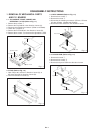
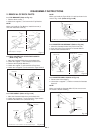
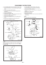
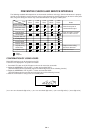
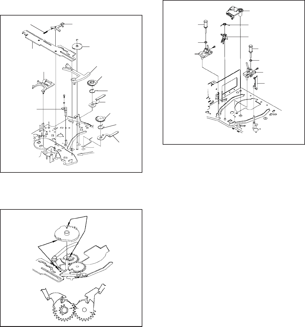
2-19: LOADING GEAR S/T ASS'Y (Refer to Fig. 2-19-A)
Remove the E-Ring 1 and remove the Main Loading
Gear.
Remove the Capstan Brake Spring.
Slide the Main Rod and remove the Capstan Brake
Arm Ass'y.
Remove the Main Rod.
Remove the Tension Lever.
Unlock the 2 supports 2 and remove the Clutch Lever.
Remove the screw 3 and washer 4.
Remove the LED Reflecter.
Remove the Loading Arm S Ass'y and Loading Arm T
Ass'y.
Remove the Loading Gear S and Loading Gear T.
Remove the Loading Gear Spring.
1.
2.
3.
4.
5.
6.
7.
8.
9.
10.
11.
1
2
2
3
Loading Gear T
Capstan Brake Arm Ass'y
Capstan Brake Spring
Main Loading Gear
Main Rod
Tension Lever
Clutch Lever
Loading Arm T Ass'y
Loading Gear S
LED Reflecter
Fig. 2-19-A
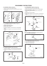
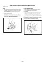
NOTE
When you install the Loading Arm S Ass'y, Loading Arm T
Ass'y and Main Loading Gear, align each marker. (Refer
to Fig. 2-19-B)
Loading Arm T Ass'y
Main Loading Gear
Marker
Marker
Loading Arm S Ass'y
Fig. 2-19-B
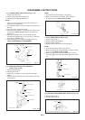
4
Loading Arm S Ass'y
Loading Gear
Spring
Loading Gear
Spring
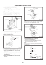
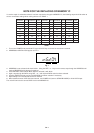
2-20: INCLINED S/T ASS'Y (Refer to Fig. 2-20)
Unlock the support 1 and remove the P4 Cover.
Remove the S-S Brake Spring.
Unlock the support 2 and remove the Loading Gear
Holder.
Remove the S-S Brake Arm.
Remove the Inclined S.
Remove the Inclined T.
Remove the 2 screws 3, then remove the Guide Roller
and O-Ring.
1.
2.
3.
4.
5.
6.
7.
NOTE
Do not touch the roller of Guide Roller.
3
2
S-S Brake Spring
Guide Roller
Loading Gear Holder
S-S Brake Arm
O-Ring
Inclined S
• Screw Torque: 0.7 ± 0.2kgf•cm
Fig. 2-20
3
O-Ring
Guide Roller
Inclined T
P4 Cover1
B2-5