


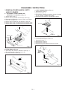
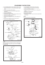
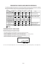
DISASSEMBLY INSTRUCTIONS
1
2
3
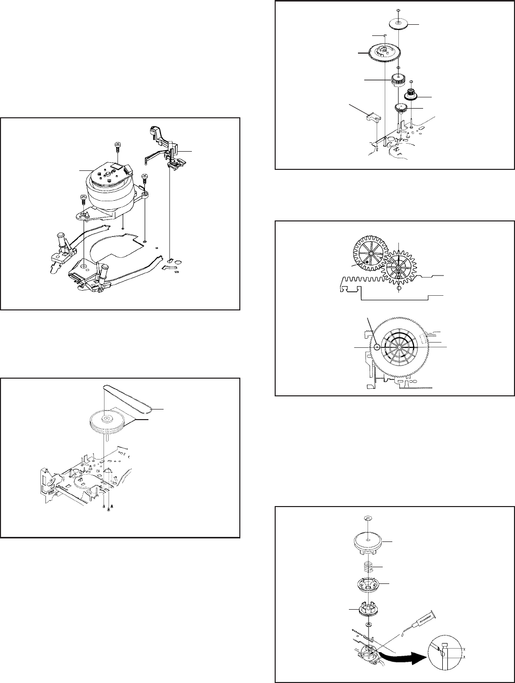
E-Ring
Middle Gear
Main Cam
Pinch Roller Cam
Link Lever Spacer
Joint Gear
P5 Cam
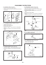
Fig. 2-17-A
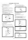
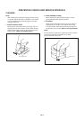
NOTE
When you install the Pinch Roller Cam, P5 Cam and Main
Cam, align each marker. (Refer to Fig. 2-17-B)
Pinch Roller Cam
P5 Cam
Main Cam
Marker
Check the hole of Main
Chassis can be seen.
Fig. 2-17-B
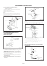
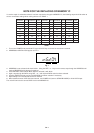
2-18: CLUTCH ASS'Y (Refer to Fig. 2-18)
Remove the Polyslider Washer 1.
Remove the Clutch Ass'y, Ring Spring, Ring Clutch,
Gear Clutch and Polyslider Washer 2.
1.
2.
NOTE
When you install the Clutch Ass'y, oil the shaft (KYODO
OIL Slidas #150).
1
Clutch Ass'y
Ring Spring
Ring Clutch
Gear Clutch
2
Fig. 2-18
App. 5mm
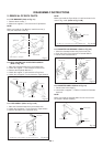
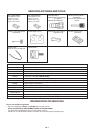
2-15: AHC ASS'Y/CYLINDER UNIT ASS'Y
(Refer to Fig. 2-15)
Unlock the support 1 and remove the AHC Ass'y.
Remove the 3 screws 2.
Remove the Cylinder Unit Ass'y.
1.
2.
3.
When you install the Cylinder Unit Ass'y, tighten the
screws from (1) to (3) in order while pulling the Ass'y
toward the left front direction.
NOTE
2
(3)
2
(1)
2
(2)
Cylinder Unit Ass'y
1
AHC Ass'y
• Screw Torque: 5 ± 0.5kgf•cm
Fig. 2-15
2-16: CAPSTAN DD UNIT (Refer to Fig. 2-16)
Remove the Capstan Belt.
Remove the 3 screws 1.
Remove the Capstan DD Unit.
1.
2.
3.
1
1
1
Capstan Belt
Capstan DD Unit
• Screw Torque: 5 ± 0.5kgf•cm
Fig. 2-16
2-17: MIDDLE GEAR/MAIN CAM (Refer to Fig. 2-17-A)
Remove the Polyslider Washer 1, then remove the
Middle Gear.
Remove the E-Ring, then remove the Main Cam, Link
Lever Spacer and P5 Cam.
Remove the Polyslider Washer 2, then remove the
Pinch Roller Cam.
Remove the Polyslider Washer 3, then remove the
Joint Gear.
1.
2.
3.
4.
B2-4