


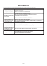
MECHANICAL ADJUSTMENTS
2-3:2-2:
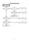
When the Tape Running Mechanism does not work well,
adjust the following items.
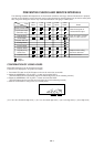
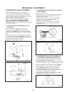
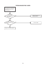
CONFIRMATION AND ADJUSTMENT OF AUDIO/
CONTROL HEAD
1.
2.
3.
4.
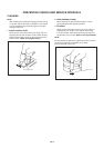
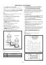
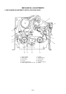
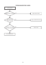
When the height is not correct, turn the screw 3 to
adjust the height. Then, adjust the 1~3 again.
Playback the VHS Alignment Tape (JG001C or JG001E).
(Refer to SERVICING FIXTURE AND TOOLS)
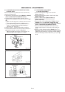
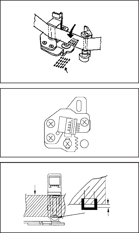
Confirm that the reflected picture of stamp mark is
appeared on the tape prior to P4 Post as shown in Fig. 2-
2-A.
a)
b)
Turn the screw 2 to set the audio level to maximum.
Confirm that the bottom of the Audio/ Control Head and
the bottom of the tape is shown in Fig. 2-2-C.
c)
When the reflected picture is distorted, turn the screw
1 clockwise until the distortion is disappeared.
When the reflected picture is not distorted, turn the
screw 1 counterclockwise until little distortion is
appeared, then adjust the a).
Reflected picture of
Stamp Mark
Stamp Mark
Audio/Control Head
P4 Post
Fig. 2-2-A
Audio/Control Head
1
3
2
Fig. 2-2-B
Tape
Audio/Control Head
Fig. 2-2-C
0.25±0.05mm
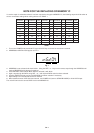
TAPE RUNNING ADJUSTMENT
(X VALUE ADJUSTMENT)
Confirm and adjust the height of the Reel Disk.
(Refer to item 1-1)
Confirm and adjust the position of the Tension Post.
(Refer to item 1-2)
Adjust the Guide Roller. (Refer to item 2-1)
Confirm and adjust the Audio/Control Head.
(Refer to item 2-2)
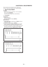
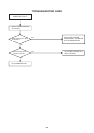
Connect CH-1 of the oscilloscope to TP4001, CH-2 to
TP4002 and CH-3 to HOT side of Audio Out Jack.
Playback the VHS Alignment Tape (JG001U or JG001V).
(Refer to SERVICING FIXTURE AND TOOLS)
Press and hold the TRACKING-AUTO button on the
remote control more than 2 seconds to set tracking to
center.
Set the X Value adjustment driver (JG153) to the 4 of
Fig. 2-2-B. Adjust X value so that the envelope waveform
output becomes maximum. Check if the relation between
Audio and Envelope waveform becomes (1) or (2) of Fig.
2-1-A.
1.
2.
3.
4.
5.
6.
7.
8.
4
D1-3