


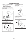
DISASSEMBLY INSTRUCTIONS
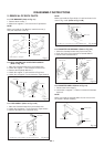
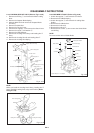
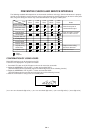
2-6: LINK ASS'Y (Refer to Fig. 2-6)
Set the Link Ass'y to the Eject position.
Remove the (A) side of the Link Ass'y first, then remove
the (B) side.
1.
2.
Main Chassis
(A)
Main Chassis
Link Ass'y
Fig. 2-6
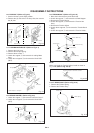
2-7: LOADING MOTOR ASS'Y (Refer to Fig. 2-7)
Remove the Link Lever.
Remove the Dumper Spring.
Remove the 2 screws 1.
Unlock the support 2 and remove the Loading Motor
Ass'y.
Unlock the 2 supports 3 and remove the Deck PCB
(BOT).
1.
2.
3.
4.
5.
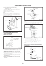
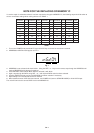
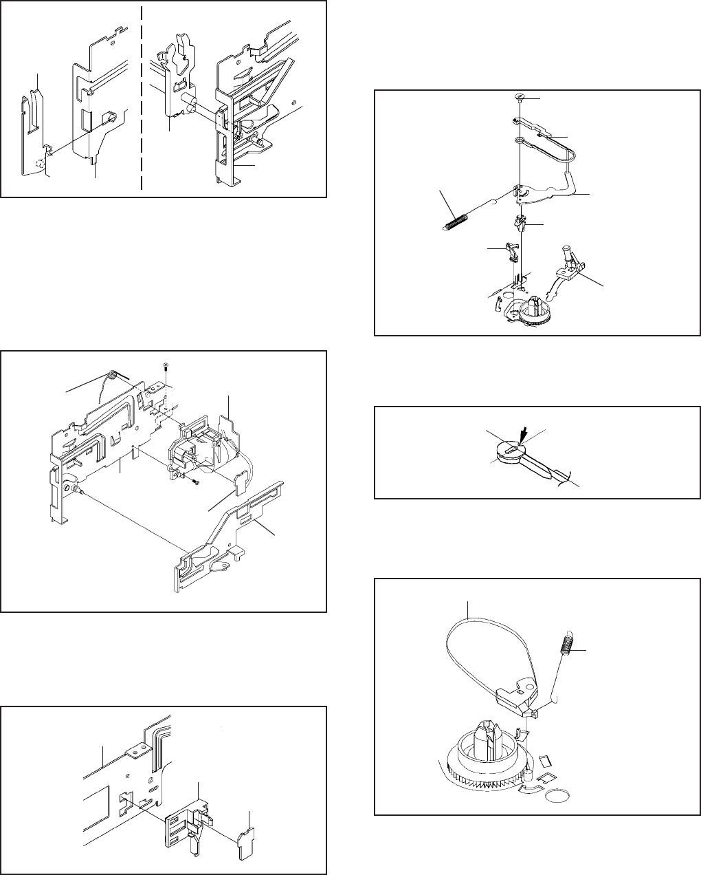
2-9: TENSION ASS'Y (Refer to Fig. 2-9-A)
Move the Inclined S Ass'y to the back side.
Unlock the support 1 and remove the S Reel Stopper.
Remove the Tension Spring.
Unlock the support 2 and remove the Tension Arm
Ass'y.
Remove the Tension Adjust.
Unlock the 2 supports 3 and remove the Tension Band
Ass'y.
Unlock the support 4 and remove the Tension Holder.
1.
2.
3.
4.
5.
6.
7.
Tension Holder
4
2
Tension Adjust
Tension Band Ass'y
Tension Arm Ass'y
1
Tension Spring
Inclined S Ass'y
Fig. 2-9-A
NOTE
When you install the Tension Adjust, install as shown in
Fig. 2-9-B. (Refer to Fig. 2-9-B)
Adjust the direction of the Marker to inside.
Fig. 2-9-B
2-10: T BRAKE ASS'Y (Refer to Fig. 2-10)
Remove the T Brake Spring.
Remove the T Brake Ass'y.
1.
2.
T Brake Ass'y
Fig. 2-10
S Reel Stopper
3
3
T Brake Spring
1
2
1
Loading Motor Ass'y
Link Lever
Main Chassis
• Screw Torque: 5 ± 0.5kgf•cm
Fig. 2-7
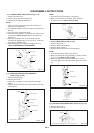
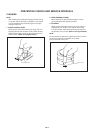
2-8: SENSOR COVER L (Refer to Fig. 2-8)
Unlock the support 1 and remove the Sensor Cover L.
Unlock the 2 supports 2 and remove the Deck PCB
(EOT).
1.
2.
Deck PCB
(BOT)
Main Chassis
Sensor Cover L
2
2
1
Fig. 2-8
Deck PCB
(EOT)
Link Ass'y
(B)
Dumper Spring
3
B2-2