


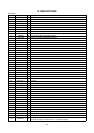
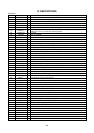
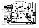
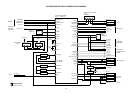
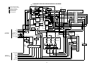
IC DESCRIPTIONS
OEC7035A
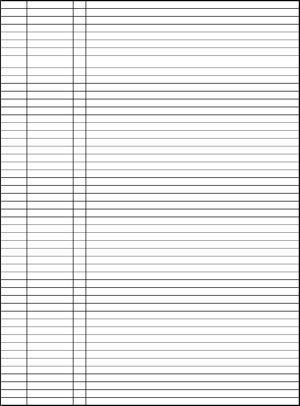
Pin No. Pin Name I/O Description
51 POWER ON L O For control the user power switch ON/OFF.
52 NC O Not used.
53 ONE TOUCH PB O Control the LED for the ONE TOUCH PLAYBACK.
54 PELI CTL I Control the 21 pin IC output.
55 NC O Not used.
56 NC O Not used.
57 A.MUTE-H O
This pin output the HIGH to mute the sound at the switching point
between E-E and V-V durin
g
the special playback.
58 T.A.MUTE-H O Not used.
59 TAB SW I Input of TAB SW.
60 NC I Not used.
61 SD O Not used.
62 CAP ON O Control the Capstan Motor rotation direction.
63 CG-CS O Output the CS signal of character generator IC.
64 FLD-CS I User switch for the auto start ON/OFF.
65 FLD-D OUT O Timing output of data transmission and receiving with FIP driver.
66 FLD-D IN I Receiving of Key switch data from FIP driver.
67 FLD-CLK O Indication data and mode transmission to FIP driver.
68 CG-DATA O Output the Data of OSD.
69 NC I Not used.
70 CG-CLK O Output the Clock of OSD.
71 IIC-CLK O Clock output to Hi-Fi IC.
72 IIC-SDA I/O DATA input/output to Hi-Fi IC.
73 32K MONI O Output 32.768KHz monitor(16.384KHz output) to check the clock.
74 Hi-Fi MUTE O Control the Hi-Fi IC.
75 V-REC-ST O Control the Head Amp for video and Hi-Fi audio.
76 PICTURE CTL O Output pulse to control the Y/C IC for sharpness.
77 CAP-CTL O Output servo of the capstan motor.
78 CYL-CTL O Output "L" when fast forwarding or rewinding.
79 REEL-S I Input terminal of reel sensor supply.
80 REEL-T I Input terminal of reel sensor take up.
81 NC - Not used.
82 P.FAIL I Input for the detection of power interruption.
83 NC - Not used.
84 C SYNC I Input Compound synchronized signal.
85 CFG I Input terminal for Capstan FG signal detection.
86 DPG I Input terminal for Drum PG signal detection.
87 DFG I Input terminal for Drum FG signal detection.
88 AMP VSS - Ground.
89 AMP V.OUT O Output the Analogue Amp standard voltage.
90 AMP V.IN I Input the Analogue Amp standard voltage.
91 CTL- I/O Input and output terminal of CTL AMP.
92 CTL+ I/O Input and output terminal of CTL AMP.
93 CTL SW OUT O Output terminal of CTL AMP positive.
94 CTL AMP IN I Input terminal of CTL AMP.
95 AMP C - Ground.
96 CTL VSS - Connect the VSS.
97 CTL AMP OUT I/O Output terminal of CTL AMP circuit.
98 CTL VCC - 5V.
99 A VCC - Voltage terminal for general circuit.
100 NC I Not used.
F-2