


E-8
E-8
E-9
English
fm
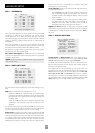
VCR OUT. Connect this to the S-video input of your video
recorder.
fl
TAPE. If you are using the tape loop for a second VCR then connect
the S-video from the VCR to this input.
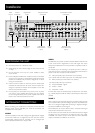
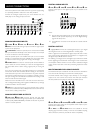
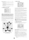
HIGH QUALITY (COMPONENT) VIDEO
CONNECTIONS
These inputs are suitable for connection to component (YUV/ YCrCb)
or RGB outputs. These signals are usually available from a DVD player,
set-top box or games console and offer the best possible picture
quality.
Generally, the component video standard is used in North America/
NTSC regions, while RGB is used in Europe.
Y/G U/B V/R Y/G V/R
1
2
V/R Y/G U/B V/R
OUT
3
fr
U/BY/G
U/B
fs
ftgk
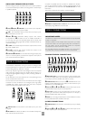
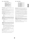
HIGH QUALITY VIDEO
fr
VIDEO 1,
fs
VIDEO 2,
ft
VIDEO 3 INPUTS. Connect these to
the video outputs of your high quality video sources.
gk
HIGH QUALITY VIDEO OUT. Connect these sockets to the
component video inputs of your display device.
Important notes about HQ video inputs and outputs
When you connect your devices to these connectors, take care to
follow the letter/colour coding for each input. No damage will occur if
incorrectly connected, but unusually coloured or unstable pictures will
result.
In the ‘Video Settings’ setup menu, each of these three high quality
component video inputs can be individually allocated to one of the
following inputs: DVD, SAT, TUNER, TAPE, CD, VCR or AV.
You cannot mix component and RGB sources.
The high quality component video inputs have sufficient bandwidth for
line-doubled NTSC (525/60) or PAL (625/50) video and US HDTV
video signals. However, when used with such signals the OSD is not
overlaid on the picture but is output at standard interlaced NTSC or
PAL (525 or 625 line) rate on a solid background.
Initially, the high quality video inputs are all disabled. Before any HQ
video input can be selected it must be allocated to an input.
RGB 4-wire connection
Some video projectors and most European TV sets require the use of
a 4-wire RGB connection, where the ‘sync’ signal is separate from RGB.
In this case, you need to use the composite video MONITOR OUT 2
for the sync information. A special cable is available from your dealer
for 4-wire RGB connection (refer to the table of SCART connections
at the back of the manual).
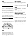
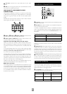
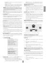
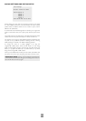
CONTROL CONNECTIONS
gl gn
gm go
OUT
IN
LOCAL
12V
TRIGGER
IN
ZONE
2
REMOTE
GROUND
LIFT (IN)
RS232
CONTROL
85 – 265VAC
MAX 40VA
gq
gn
IN LOCAL. Use with a local IR receiver when the AV8 front panel
IR receiver is obstructed.
go
IN ZONE 2. This allows the AV8 to be controlled remotely from
zone 2 via infrared remote control.
A receiver compatible with this connector is available from Xantech
(part no. 291-10). Please contact a Xantech registered dealer for this
part, as ARCAM do not stock them. See www.xantech.com for more
information.
The 3.5mm jack plug for this connector is wired as follows:
3.5mm stereo jack Function
Tip Signal
Ring 0V
Sleeve 12V, 30mA current-limited
This follows the Xantech standard for IR transmission over wire.
Connect to a remote IR receiver in zone 2 to allow control of the AV8
from zone 2.
gl
(REMOTE) OUT. This enables control of the source components
remotely from zone 2 or zone 1 using the local input. Control is
possible by either connecting to the source devices via the 3.5mm IR
jack (Arcam units only) or using an IR emitter stuck to the centre of
the IR sensor window on the source component (such as a Xantech
283MW mini emitter).
gq
RS232 CONTROL Use with control devices having an RS232 serial
port (for example, Crestron and AMX touch screen controllers). This
connection is also used for upgrading control software. See the sections
at the end of this manual for control and programming information.
TRIGGER OUTPUTS
There are three trigger output sockets on the AV8, each of which is a
3.5mm stereo jack with two contacts, ‘tip’ and ‘ring’. See the tables for
technical information on the trigger outputs.
gm
12V TRIGGER. Use for remotely turning on and off power amps or
source equipment for the main zone and zone 2.
3.5mm stereo jack Function Voltage
Tip Main zone on On = 12V, 30mA
Off = 0V
Ring Zone 2 on On = 12V, 30mA
Off = 0V
Sleeve Ground 0V