


19
English
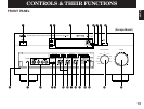
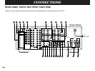
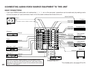
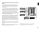
1 OPTICAL Digital Input and Output Jacks
Can be connected with audio/video units that have optical digital
signal output (and input) jacks.
2 COAXIAL Digital Input Jack (for CD Player)
Can be connected with a CD player that has a coaxial digital
signal output jack.
3 AC-3 RF SIGNAL Input Jack (for LD player)
Can be connected with an LD player that has an AC-3 RF audio
signal output jack.
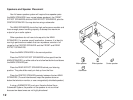
4 GND Terminal
Connects the ground wire of the turntable to produce minimum
hum. In some cases, however, better results may be obtained
with the ground wire disconnected.
5 AUDIO SIGNAL Connection Jacks (for Audio Source Equipment)
Connect the inputs and/or outputs of your audio equipment.
6 AUDIO/VIDEO SIGNAL Connection Jacks (for Video Source
Equipment)
Connect the audio and video inputs and/or outputs of your video
equipment. In place of the VIDEO jacks, the S VIDEO jacks can
be used for higher resolution and improved picture quality if your
VCR, monitor, etc. are equipped with S-VIDEO connectors.
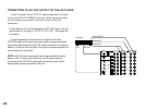
7 MAIN SPEAKERS Terminals
When using this unit’s built-in main-channel amplifier, connect the
main speakers here. The jumper bars must be plugged in to
connect the MAIN IN jacks to the PRE OUT jacks.
8 FRONT SPEAKERS Terminals
When using the built-in front-channel amplifier, connect the front
effect speakers here.
9 CENTER SPEAKERS Terminals
When using the built-in center-channel amplifier, connect one or
two center speakers here.
0 Center Speaker Impedance Switch
Set to “A + B” when using two center speakers, or to “A OR B”
when using only one center speaker.
A REAR SPEAKERS Terminals
When using the built-in rear-channel amplifier, connect the rear
effect speakers here.
B Video NTSC/PAL Switch (General Model only)
Set this switch to the position corresponding to the standard
that your video equipment employs.
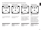
C FRONT MIX Switch
Set to “OFF (7ch)” when setting up a full 7 or 6 speaker system,
or to “ON (5ch)” when setting up a 5 or 4 speaker system.
D MAIN LEVEL Switch
Normally set to “0 dB”. If desired, you can decrease the main-
channel output level at the MAIN SPEAKERS terminals by 10 dB
by setting this switch to “–10 dB”.
E PRE OUT Jacks
Main-channel line output. Connected with jumper bars to MAIN
IN jacks when the built-in amplifier is used. Connected to input
jacks of external stereo power amplifier (MAIN IN or TAPE PLAY
jacks of integrated amplifier or receiver) when using external
amplification.
F MAIN IN Jacks
Line input to built-in main-channel amplifier. Connected with
jumper bars to PRE OUT jacks when the built-in amplifier is used.
Not connected when using an external power amplifier.