


14
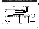
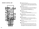
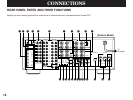
1 POWER Switch
Turns this unit on and off.
2 Standby Indicator (Europe, U.K. and Australia models only)
While the power of this unit is on, pressing the POWER key on
the remote control unit switches this unit to the standby mode. In
this mode, the standby indicator is half illuminated.
3 Remote Control Sensor
Signals from the remote control unit are received here.
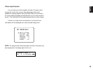
4 Display Panel
Shows program names, parameters and information for various
setting changes and adjustments.
5 AC-3 Indicator
Lights up while the built-in Dolby Surround AC-3 Decoder is
functioning.
6 PRO LOGIC Indicator
Lights up while the built-in Dolby Pro Logic Surround Decoder is
functioning.
7 DSP Indicator
Lights up while the built-in Digital Sound Field Processor is
functioning.
8 DIGITAL SOURCE AC-3/PCM Indicator
“AC-3” lights up when a Dolby Surround AC-3 encoded signal is
input to this unit. “PCM” lights up when a digital signal other than
Dolby Surround AC-3 encoded signals is input to this unit.
9 TAPE 2 MONITOR Switch
Used when you have connected a second tape deck to this unit’s
AUDIO SIGNAL TAPE 2 jacks to select that tape as the source.
0 Control Door
See page 4 for how to open and close the control door.
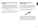
A PHONES Jack
Plug in headphones here for private listening. Sound signals
from the main channels only are output here. However, if the
Dolby Surround AC-3 is decoded, signals at all channels are
distributed to the main channels and output here.
B Auxiliary Input Jacks (VIDEO AUX)
Connect an auxiliary video or audio unit such as a camcorder
to these jacks. If the connected video unit has a S video output
terminal, connect it to the S VIDEO jack to obtain a high
resolution picture. The unit connected to these jacks can be
selected by the INPUT SELECTOR and REC OUT selector.
C BASS EXTENSION Switch
When pressed inward (ON), boosts bass frequency response
at the main left and right channels while maintaining overall
tonal balance. If you do not have a subwoofer, the use of this
switch will be effective to reinforce the bass frequencies.
*
The use of this switch will not be so effective if you set the
function “1. SPEAKER SET” in the SET MENU mode to
output low bass signals at the main channels from the
subwoofer only. (See pages 30–32 for details.)
D INPUT TRIM Control
Adjusts the input level of each source respectively. Moreover,
performs setting changes and adjustments for functions
selected in the SET MENU mode.
E SET MENU Switch
Whenever pressed, selects functions in the SET MENU mode.