


Using The TPA005D12 Class-D EVM Stand-Alone
3-19
Details
3.5.2 Input Connections
The class-D amplifier input signals can be connected in either of two ways:
differential or single-ended. For differential operation, connect the two lines
from the signal source to the positive and negative inputs of each channel
(RIN+/RIN– and LIN+/LIN– module pins). For single-ended operation, the
input signal lines should be connected to the RIN+ and LIN+ module pins and
the signal source ground wires should be connected to the RIN– and LIN–
module pins.
For best results, the ground of the signal source should be connected to the
GND pins at the EVM inputs to provide a return path for the current. The input
signal and ground wires should be twisted to reduce inductance and noise
pickup if the lead lengths are long and the cable is not shielded.
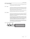
3.5.3 Output Connections
The right speaker should be connected between the Rout+ and the Rout–
module pins, and the left speaker should be connected between the Lout+ and
the Lout– module pins to comply with the isolated output requirements for BTL
operation.
3.5.4 Controls and Indicators
The mute and shutdown functions may be controlled externally via the module
mute and SD pins. An active-low input mutes the selected amplifier or shuts
down the device. A signal of 2 V or higher, or a float condition, allows normal
operation.
Note that the mute and shutdown signals applied to the EVM control input pins
must be able to supply enough current to overcome the pullup resistor on the
module (100 kΩ).
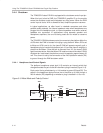
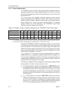
The fault indicator circuit can be monitored by attaching a pullup resistor to the
open-drain outputs of FAULT0 (TP2) and FAULT1 (TP3). The voltage should
not exceed 5 V and the current must be limited to less than 1 mA. A fault table
is shown in Section 3.2.5 and the device data sheet.