


The TPA005D12 Class-D Audio Power Amplifier Evaluation Module
3-5
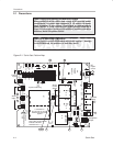
Details
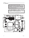
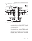
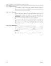
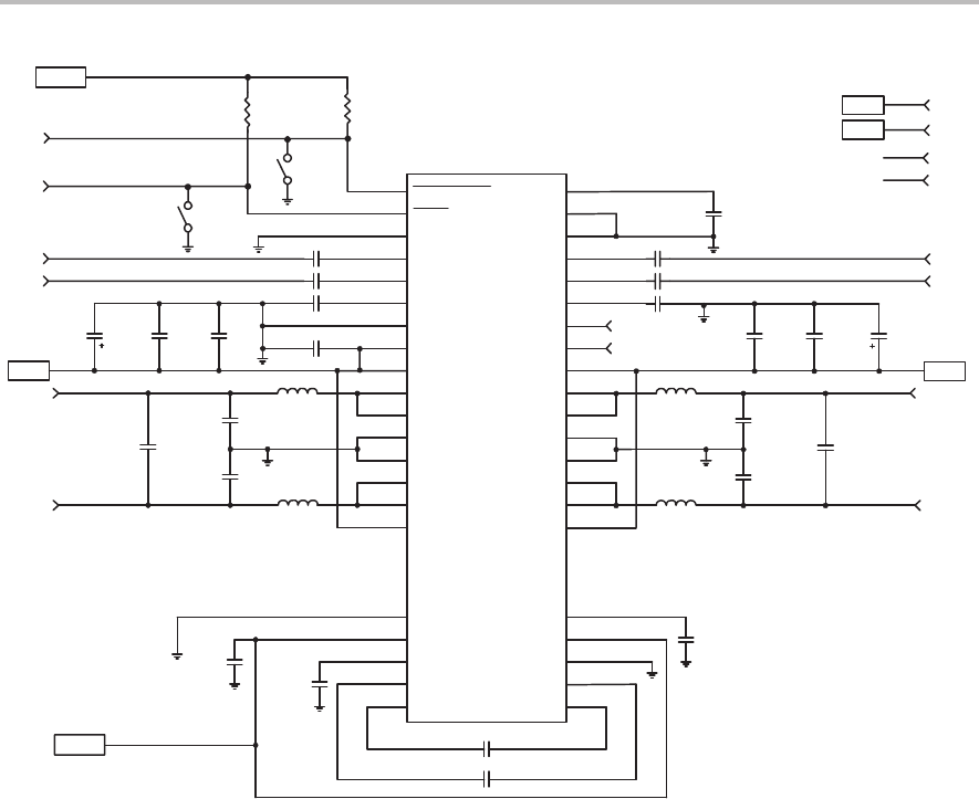
Figure 3–4. TPA005D12 Class-D EVM Schematic Diagram
TPA005D12
S2
SD
R2
100k
SD
R1
100k
S1
Mute
Mute
VDD
C3
LOUTP
11
PGND
12
PGND
13
LOUTN
14
LOUTN
15
LPVDD
16
NC
17
NC
18
LOUTP
10
LPVDD
9
VDD
8
AGND
7
LCOMP
6
LINP
5
LINN
4
NC
19
AGND
20
PVDD
21
VCP
22
CP3
23
CP2
24
AGND
3
2
SHUTDOWN
1
MUTE
ROUTP
38
PGND
37
PGND
36
ROUTN
35
ROUTN
34
RPVDD
33
NC
32
NC
31
ROUTP
39
RPVDD
40
FAULT_1
41
FAULT_0
42
RCOMP
43
RINP
44
RINN
45
NC
30
V2P5
29
PVDD
28
PGND
27
CP4
26
CP1
25
AGND
46
47
COSC
48
AGND
C18
C19
C8
C2
C6
LIN–
LIN+
L3
L1
C21
C20
C24
C13 C9 C10
LOUT+
LOUT–
VDD
C4
C7
RIN–
RIN+
L4
L2
C22
C23
C25
C14C12C11
ROUT+
ROUT–
VDD2
C1
C5
TP2
TP3
C16
10µF
1µF
1µF
1µF
1µF
470pF
+5V
VDD
+5V
VDD2
15µH
15µH
1µF
0.22µF
0.22µF
0.047µF
0.047µF
1µF
1µF
1µF
1µF
1µF
470pF
470pF
10µF
15µH
15µH
0.22µF
0.22µF
C17
0.1µF
C15
1µF
TP2
TP3
VDD
3.2.1 TPA005D12 Class-D Stereo Audio Amplifier IC
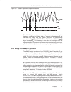
The TPA005D12 class-D stereo audio power amplifier integrated circuit
converts low-level audio into pulse-width-modulated (PWM) signals, which
result in an audio output with a 20-dB increase in amplitude. The IC features
high-current DMOS output transistors and internal feedback that provides
excellent performance without the need for external components (beyond
input isolation and output filtering).
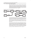
A full range of protection features are built into the TPA005D12 amplifier IC to
increase device reliability: thermal, overcurrent, and undervoltage shutdown,
with status terminals that report any error conditions encountered.
The device is provided in a very small 48-pin thermally-enhanced PowerPAD
TSSOP surface-mount package (DCA) and consumes only 1 µA in the
shutdown mode, making the TPA005D12 an excellent choice for portable
battery-powered applications.