


Using The TPA005D12 Class-D EVM With the Plug-N-Play Platform
3-13
Details
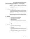
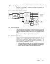
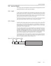
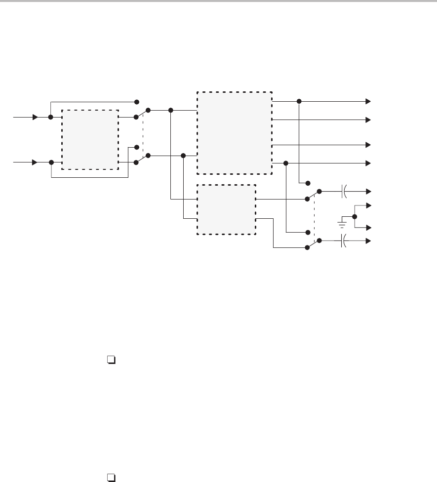
3.4.3 Signal Routing
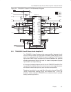
Signal flow on the platform is controlled by two signal routing switches, as
shown in Figure 3–7.
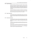
Figure 3–7. Platform Signal Routing and Outputs
U1
Signal
Conditioning
On
Off
U5
Stereo
Headphone
Amplifier
S2
R
L
R
L
L
U5
U2–U4
S3
J10
Headphone
Output
R
L
Audio
Input
R
L
J7, J8, J9
Speaker
Outputs
R
+
+
–
–
U2/U3
TPA005D12
Amplifier EVM
+
+
–
–
GND
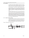
3.4.3.1 Signal Conditioning
The audio signal from input jacks can be applied to the signal conditioning
socket (U1) if an EVM is installed there, or socket U1 can be bypassed and the
audio input signal applied directly to the inputs of the TPA005D12 class-D
EVM.
Platform switch S2 selects signal conditioning or bypasses it.
3.4.3.2 Headphone Output Jack
Switch S3 is the source select for the stereo headphone output jack, J10. The
headphone jack is capacitively coupled (via 470 µF electrolytics) and can
output either the signal from the headphone amplifier in socket U5, or the
signal from the power amplifier installed in socket U2, as determined by the
setting of headphone source select switch S3.
The platform headphone output jack (J10) is not used in conjunction with
the TPA005D12 class-D EVM. Switch S3 should be set to the
U5
position
when the TPA005D12 class-D EVM is installed on the platform.