


Using The TPA005D12 Class-D EVM Stand-Alone
3-18
Details
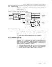
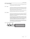
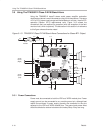
3.5 Using The TPA005D12 Class-D EVM Stand-Alone
Using the TPA005D12 class-D stereo audio power amplifier evaluation
module stand-alone is much the same as using it with the platform. The same
4.5-V to 5.5-V power supply range and the isolated out+ and out– lines for BTL
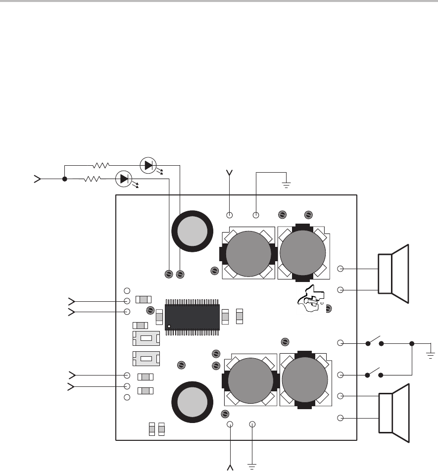
operation (Section 3.2.3) requirements exist. Figure 3–10 shows the
connections that are required for operation (with the exception of the fault
monitor circuit, which is optional). The discussion in this section is in reference
to this figure unless otherwise noted.
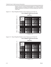
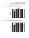
Figure 3–10. TPA005D12 Class-D EVM Stand-Alone Connections for Stereo BTL Output
5 V
5 V
Left
Right
Audio
Inputs
(Right)
Audio
Inputs
(Left)
LED 0
R
Shutdown
Mute
R
5 V
LED 1
Fault
Monitor
Texas
1999
U1
+RIN–
TP1
C5
Rout+
R2
R1
SD
Mute
Rout–
Lout+
Lout–
GND
VDD
SLOP246 TPA005D12 EVM Board
GND
VDD2
Instruments
GND
–LIN+GND
S1
Mute
S2
SD
C1
C4
C3
C2
C18
L4
L3
L2
L1
TP11
TP10
C14
TP7
TP3
TP2
TP12
TP5
TP6
TP4
C13
+
+
TP9
TP8
C19
3.5.1 Power Connections
Power must be connected to both the VDD and VDD2 module pins. Power
supply ground can be connected to any module ground pin, although best
results are achieved if power supply grounds are connected to the pins
adjacent to the VDD and VDD2 module pins. The ground and power wires
should be twisted to reduce inductance and noise pickup if they are long.