WFM 90 and WFM 91 Service Manual
9–1
Diagrams
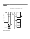
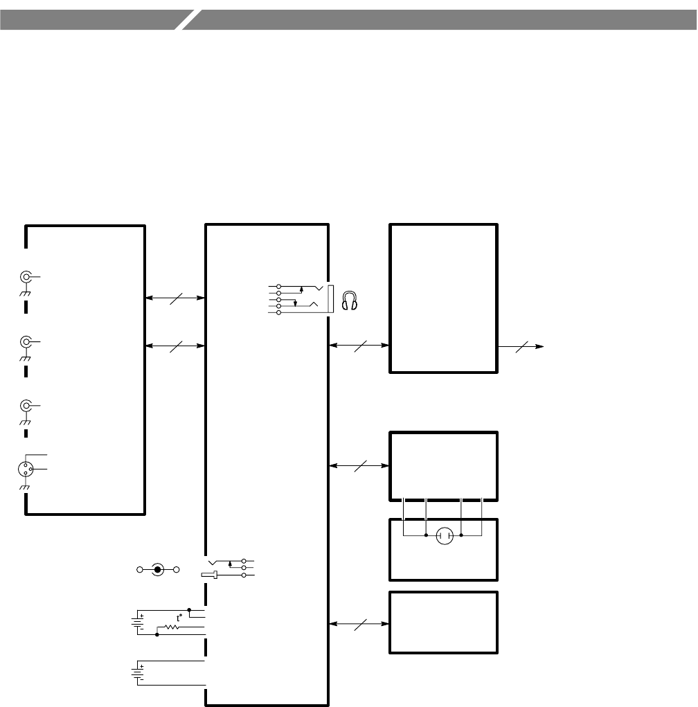
This section contains the interconnect diagram for the WFM 90 and WFM 91
Handheld Waveform, Vector, Picture, and Audio Monitor.
A3 Bottom
Board
10
A1 Input
Board
60
10
J9J2
J20
J19
J11
A2 Top Board
12
20
J16
A5 LCD Display
Module
Video In
J4
Ref In
J5
Video Out
J6
Audio In
J7
J14
10
J12 J15
A4 Backlight
Board
W4W3W2W1
J13
J10
J21
J17
DC in 11–18V
Test only
Backlight
J25
NiCad Battery Pack
6 C Cell Batteries
Figure 9–1: Interconnect diagram


