


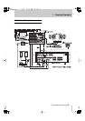

2 - Rear panel
TASCAM MD-801R/P Mk II
2–8
ital outputs
[33]
and
[35]
without passing through
the frequency converter.
[33]DIGITAL OUTPUT (AES/EBU)
This XLR-type connector outputs digital audio data
in AES3-1992 format.
The output sampling frequency will always be
44.1 kHz, ±9.9%, as determined by the pitch control
(see both 4.2.13, "Varispeed mode" and 3.2, "Pitch
control").
[34]DIGITAL INPUT (COAXIAL)
This RCA connector accepts digital audio data in
IEC 60958 (consumer) format (SPDIF).
The input sampling frequency can be 32 kHz,
44.1 kHz or 48 kHz. The MD-801’s internal sam-
pling frequency converter will convert them all to
44.1 kHz for recording.
If switch 4 of the
MODE SET
DIP switch bank
[43]
is set off, the signals input here are echoed at the dig-
ital outputs
[33]
and
[35]
without passing through
the frequency converter.
[35]DIGITAL OUTPUT (COAXIAL)
This RCA connector outputs digital audio data in
IEC 60958 (consumer) format (SPDIF).
The output sampling frequency will always be
44.1 kHz, ±9.9%, as determined by the pitch control
(see both 4.2.13, "Varispeed mode" and 3.2, "Pitch
control").
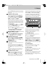
[36]ANALOG INPUTS and trimmers
(BALANCED)
These XLR-type connectors accept balanced analog
signals at professional (+4 dBu) levels.
The wiring is, as marked on the rear panel:
1=ground, 2=hot (+), 3=cold (–).
The nominal impedance is 2.2 k
Ω
.
The trimmer potentiometers by each connector may
be turned counterclockwise or clockwise to cut or
boost respectively the level of the signal received at
the inputs. The maximum cut achievable (relative to
nominal) is –4 dB and the maximum boost is +7 dB.
As shipped, the trimmers are set to the standard
+4 dBu level.
[37]ANALOG INPUTS (UNBALANCED)
These RCA connectors accept unbalanced signals at
the –10 dBV level.
The nominal impedance is 8 k
Ω
.
[38]ANALOG OUTPUTS (MONITOR)
These RCA unbalanced connectors provide output
signals at the –10 dBV level.
The nominal impedance is 220
Ω
.
[39]Analog output function DIP switch
bank
This bank of four DIP switches is used to control the
outputs from the
MONITOR
and
LINE
analog out-
puts
[38]
and
[40]
.
They have the following meanings:
NOTE
The
PHONES
output
[9]
is always active,
regardless of the settings made using these
switches.
[40]ANALOG OUTPUTS (LINE) and
trimmers
These XLR-type connectors output balanced analog
signals at professional (+4 dBu) levels.
R
R
R
No
OFF
(up)
ON
(down)
1
STEREO
MONO
Allows the output mode from both
the
LINE
and the
MONITOR
out-
puts to be set to
MONO
or
STEREO
, as well as output from
the
PHONES
jack.
2
SYNCHRONIZE
INDIVIDUAL
When set to
SYNCHRONIZE
, the
LINE
and
MONITOR
outputs are
paralleled. When set to
INDIVIDUAL
, signals are output
from the
MONITOR
outputs only
when the
PLAY
key on the MD-801
itself, or the
MONITOR
key on the
optional RC-801 is pressed. To out-
put signals from the
LINE
outputs
when this switch is set to
INDIVIDUAL
, use the
ONLINE
key on the optional RC-801, or
send a “play” command from a
remote controller connected to the
serial or parallel interface.
3
LINE MON OFF
LINE MON ON
When
OFF
, whether the
MONITOR
outputs output a signal depends on
the setting of switch 2 in this bank
(i.e. if switch 2 is on, the
MONITOR
outputs are only active
when the MD-801’s
PLAY
key has
been pressed). When
ON
, monitor-
ing is always on, regardless of from
where the play command origi-
nated.
4 Reserved—leave in the
OFF
position