User's Manual
14
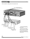
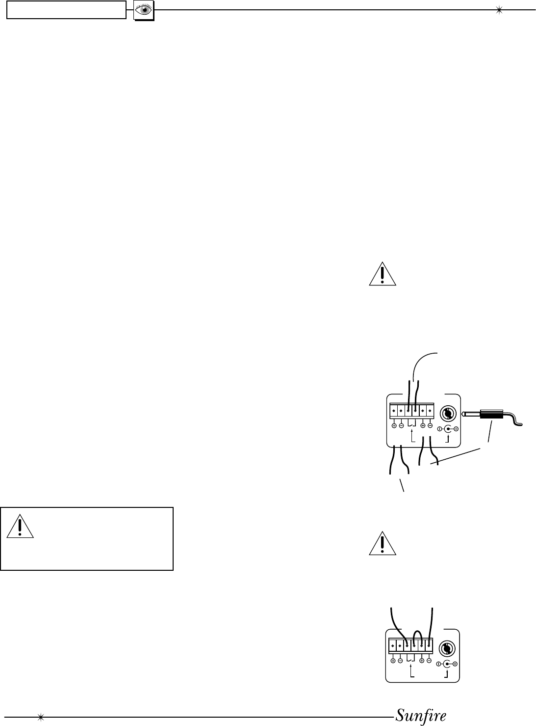
+12V
GND
USE EITHER
TO TURN
MAIN ZONE
AMPLIFIER ON
USE TO TURN
ZONE TWO
AMPLIFIER ON
+12V
GND
THIS TRIGGER RELAY IS
NORMALLY OPEN.
IT CLOSES WHEN YOU SELECT
ANY INPUT WHOSE TRIGGER
HAS BEEN ENABLED
ZONE2
12VDC
MAIN ZONE
TRIGGERS
12VDC
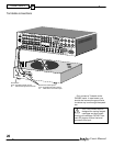
+12V
GND
+12V IS PRESENT WHEN AN INPUT WHOSE
TRIGGER IS ENABLED IS SELECTED
ZONE2
12VDC
MAIN ZONE
TRIGGERS
12VDC
CHAPTER 1
Observe the following precautions
when choosing a location for your
TGIII:
• Protect it from pro longed
ex po sure to direct sunlight and
other direct sources of heat,
such as heating vents and
ra di a tors.
• Do not expose the unit to rain
or moisture. If fl uid or a for-
eign object should enter the
unit, immediately turn off the
power and contact your Sunfi re
Dealer.
• Avoid excessive exposure to
extreme cold or dust.
• Do not place heavy objects on
top of the unit.
AC Power Con sid er ations
Ensure that the unit is plugged into
an outlet capable of supplying the cor-
rect voltage specifi ed for your model.
Care
If you need to clean the front sur-
face, fi rst turn off the power and then
use a soft dry cloth, rubbing with the
grain. Be careful not to scratch the
display window.
Connection Tips
Before setting up your new sys tem,
please consider the following :
Always make sure that your
com po nents are all turned
OFF, or unplugged before
making or changing any
connec tions.
• Whenever possible, route the
power cords away from the
signal cables or speaker wires
to pre vent any hum or in ter -
fer ence heard in the speak ers.
• Choose reliable hookup cables.
They should be fully shield ed
and as short as pos si ble.
• Use quality coaxial digital
cables to connect the TGIII to
any source equipment which
has coaxial digital outputs.
• Some patch cords can be a
very tight fi t and there is usu-
ally a preferred method of get-
ting them off. Some have to be
removed with a twisting action.
Be gentle or you may dam age
the jacks of your TGIII, or other
com po nents.
• Some audiophile cables should
be hooked up in one direction,
these are usually marked with
arrows.
• It is usual for the right channel
patch cord plugs to be red and
the left channel con nec tions to
be white, grey or black. Com-
pos ite video con nec tions are
usually yellow.
• If your amplifi er has XLR
inputs, use balanced connec-
tions as they provide superior
rejection of hum and noise,
especially if long cables are
required.
Video Connections
The TGIII has three types of video
connections: composite video,
S-video, and com po nent video. There
are no internal con nec tions between
these three different types; if you put
a composite video signal in, you will
only get com pos ite video out. Choose
component or S-video if your video
system supports it, this will give better
picture quality than composite video.
When an audio/video component
is selected, the audio will play in your
system and the video will be switched
to a video input of your TV mon i tor.
You must have the TV connected in
order to see the On Screen
Display (OSD). Note that the OSD is
not available with component video,
just composite or S-video.
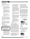
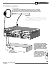
Video Screen Trigger
The Main Zone and Zone 2
12 VDC terminals each supply 12
VDC whenever that zone is turned
on. This can be used to turn on power
amplifi ers equipped with a 12 V trigger
input.
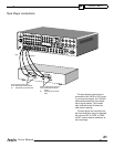
The two middle ter mi nals marked
as re lay con tacts are con nect ed to-
geth er only when the Main Zone is on
and an in put is se lect ed for which the
trigger output is enabled. The OSD
INPUTS Menu can be used to select
which inputs have the trigger output
enabled or disabled (see page 34).
Use all stan dard safe ty pre-
cau tions and make sure all
the equip ment is dis con nect ed
be fore making any con nec -
tions.
Here are two connection options:
DO NOT use the relay con-
tacts for 120 VAC or 240 VAC
switching! They are only for
low voltage AC/DC loads of
2 A maximum.
Installation


