


9-39
DFP-3000
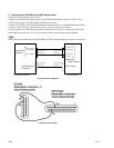
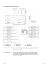
9.8.3 Actual Connection of Control System
When controlling operations of the Dolby Laboratories SA-10 (Surround EX processor) from the DFP-
D3000 (switch the Surround EX mode between ON and OFF), connect the control input connector on the
rear panel of the SA-10 and Automation connector on the DFP-D3000 as follows.
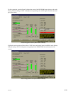
1. Settings at the SA-10 (Surround EX Processor) side
. Set the control mode switch SW1 (located on the daughter board) in the SA-10 to the “CP65” position.
. Push in (Normal position) the “Alignment Switch S602” on the rear of the SA-10 front panel.
. Set the “Surround switch” on the SA-10 front panel to the “Enable” position.
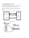
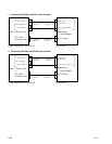
2. Connections of the Control Cable Between the DFP-D3000 and SA-10
. Connect Pin 14 (Logic Common) of the DFP-D3000 Automation connector to Pin 12 (GND) of the
Control Input connector of SA-10.
. Connect Pin 32 (SDDS OK) of the DFP-D3000 Automation connector to Pin 4 (CTRL 4, EX decode
mode) of the Control Input connector of SA-10.
. Connect Pin 36 (ACM) of the DFP-D3000 Automation connector to Pin 2 (CTRL1, non decode mode)
of the Control Input connector of SA-10.
With this connection, the signal for indicating the read state of the SDDS is sent to the SA-10 control
signal input which is the Surround EX Processor, and the SA-10 operations are controlled via the control
cable according to the SDDS signal state.