


9
EN
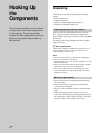
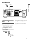
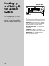
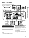
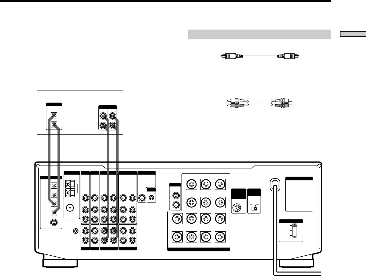
Hooking Up the Components
OUT IN IN OUT
LINE
L
R
LINE
INPUT OUTPUT
WIRELESS
REAR
SPEAKER
4 Ω 8 Ω
+
+
+–
–
+
–
–
A
R
RL
L
220 V
B
A
B
120 V
240 V
SPEAKERS
FRONT
REAR CENTER
WOOFER
AUDIO
OUT
VIDEO
OUT
VIDEO
IN
VIDEO
OUT
VIDEO
IN
DVD IN
VIDEO
OUT
VIDEO
IN
IN
L
R
RECOUT
SIGNAL
GND
COAXIAL
AM
AUDIO
IN
L
R
AUDIO
OUT
AUDIO
IN
AUDIO
OUT
AUDIO
IN
CTRL A1
y
y
ANTENNA
TAPE
MONITORVIDEO 1VIDEO 2
TV/LD DVD
S-LINK
VIDEO
IN
AUDIO
IN
OPTICAL
IMPEDANCE
SELECTOR
FRONT
VOLTAGE SELECTOR
IN
PHONO
IN
CD
INRECOUT
MD/DAT
FM
75Ω
DIGITAL
TV / LD IN
OPTICAL
MD/DAT IN
OPTICAL
MD/DAT OUT
OPTICAL
DVD IN
COAXIAL
DIGITAL
OUT
OPTICAL
IN
ç
ç
ç
ç
AC OUTLET
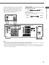
Required cords
Optical digital cords (not supplied)
Audio cords (not supplied)
When connecting a cord, be sure to match the color-coded pins to
the appropriate jacks on the components.
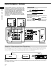
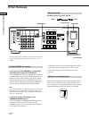
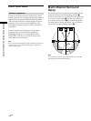
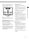
Connect the digital output jack of your MD or DAT deck
to the receiver’s digital input jack and connect the digital
input jack of your MD or DAT deck to the receiver’s
digital output jack. These connections allow you to make
digital recordings of a CDs played back through your
DVD (or LD player) and TV broadcasts.
Black Black
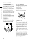
Notes
• Please note that you cannot make a digital recording of a digital multi channel surround signal.
• To make a digital recording from your CD player, connect the CD player’s digital output directly to the digital input on your MD or DAT
deck. Refer to the instructions supplied with your CD player and MD or DAT deck for details.
• This unit is compatible with 32 kHz, 44.1 kHz, and 48 kHz sampling frequencies. It is not compatible with 96 kHz sampling frequencies.
• It is not possible to record analog signals to TAPE and VIDEO with only digital connections. Be sure to make both digital and analog
connections to your digital components.
MD or DAT deck
White (L) White (L)
Red (R) Red (R)