


7
EN
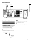
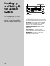
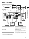
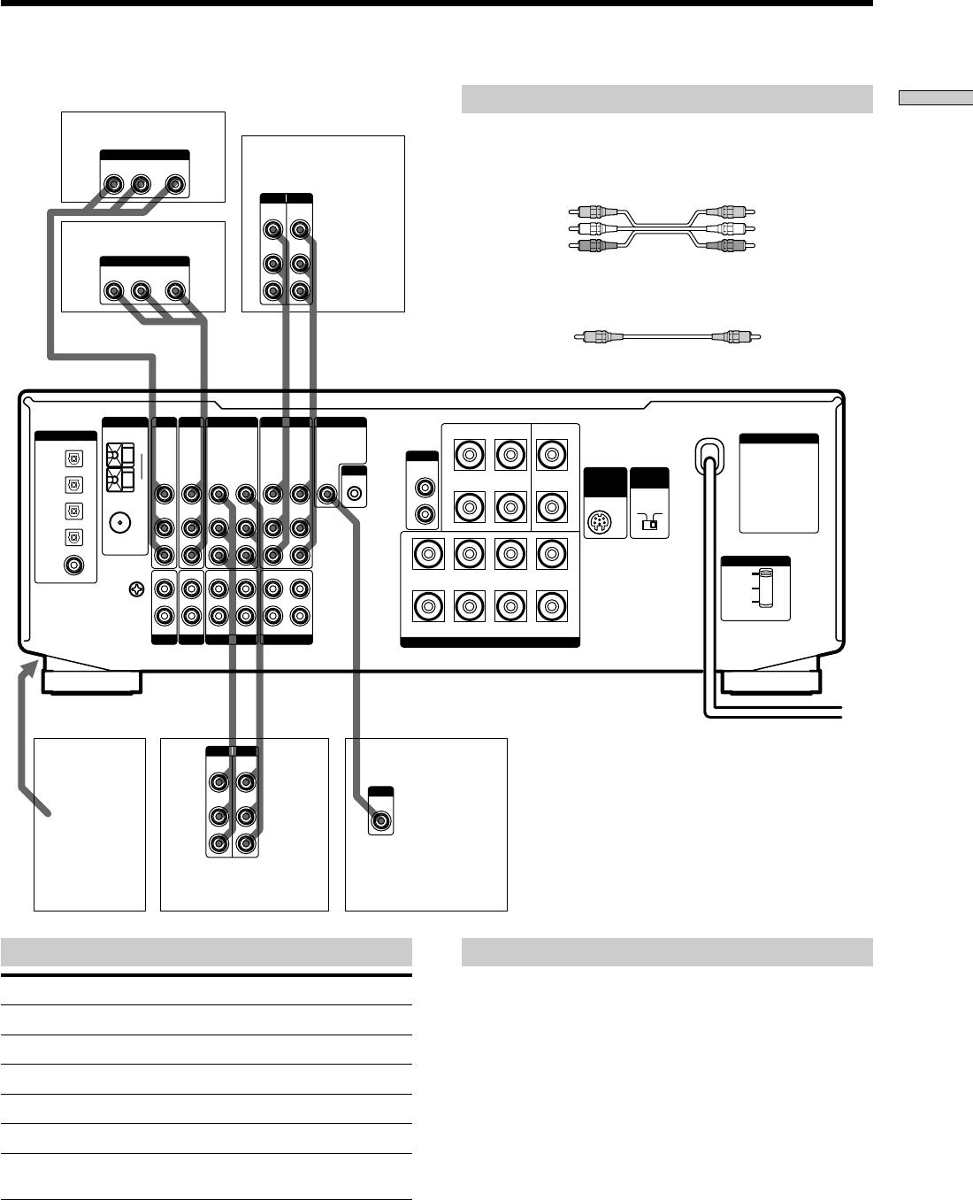
Hooking Up the Components
IN OUT
IN OUT
WIRELESS
REAR
SPEAKER
4 Ω 8 Ω
+
+
+–
–
+
–
–
A
R
RL
L
220 V
B
A
B
120 V
240 V
SPEAKERS
FRONT
REAR CENTER
WOOFER
AUDIO
OUT
VIDEO
OUT
VIDEO
IN
VIDEO
OUT
VIDEO
IN
DVD IN
VIDEO
OUT
VIDEO
IN
IN
L
R
RECOUT
SIGNAL
GND
COAXIAL
AM
AUDIO
IN
L
R
AUDIO
OUT
AUDIO
IN
AUDIO
OUT
AUDIO
IN
CTRL A1
y
y
ANTENNA
TAPE
MONITORVIDEO 1VIDEO 2
TV/LD DVD
S-LINK
VIDEO
IN
AUDIO
IN
OPTICAL
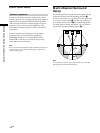
IMPEDANCE
SELECTOR
FRONT
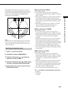
VOLTAGE SELECTOR
IN
PHONO
IN
CD
INRECOUT
MD/DAT
FM
75Ω
DIGITAL
TV / LD IN
OPTICAL
MD/DAT IN
OPTICAL
MD/DAT OUT
OPTICAL
DVD IN
COAXIAL
ç
ç
ç
ç
VIDEO
OUT
R
VIDEO
IN
AUDIO
OUT
AUDIO
IN
INPUT OUTPUT
L
VIDEO
OUT
R
VIDEO
IN
AUDIO
OUT
AUDIO
IN
INPUT OUTPUT
L
RL
AUDIO OUT VIDEO
OUT
OUTPUT
RL
AUDIO OUT VIDEO
OUT
OUTPUT
VIDEO
IN
INPUT
AC OUTLET
VCR
To the front panel
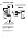
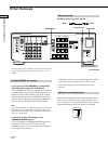
Note on video component hookups
You can connect your TV’s audio output jacks to the TV/
LD AUDIO IN jacks on the receiver and apply sound
effects to the audio from the TV. In this case, do not
connect the TV’s video output jack to the TV/LD VIDEO
IN jack on the receiver. If you are connecting a separate
TV tuner, connect both the audio and video output jacks
to the receiver as shown above.
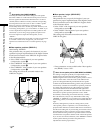
Jacks for connecting video components
Connect a To the
TV tuner or LD player TV/LD jacks
VCR VIDEO 1 jacks
Additional VCR VIDEO 2 jacks
DVD player DVD jacks
TV monitor MONITOR VIDEO OUT jack
Camcorder or video game VIDEO 3 INPUT jacks on the
front panel
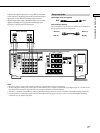
Required cords
Audio/video cords (not supplied)
When connecting a cord, be sure to match the color-coded pins to
the appropriate jacks on the components.
Video cord for connecting a TV monitor (not supplied)
Video Component Hookups
Camcorder
or video
game
VCR
TV monitor
TV tuner or LD player
DVD player
Yellow Yellow
Yellow (video) Yellow (video)
White (L/audio) White (L/audio)
Red (R/audio) Red (R/audio)