


– 21 –
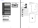
[Laser Power Check]
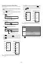
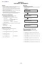
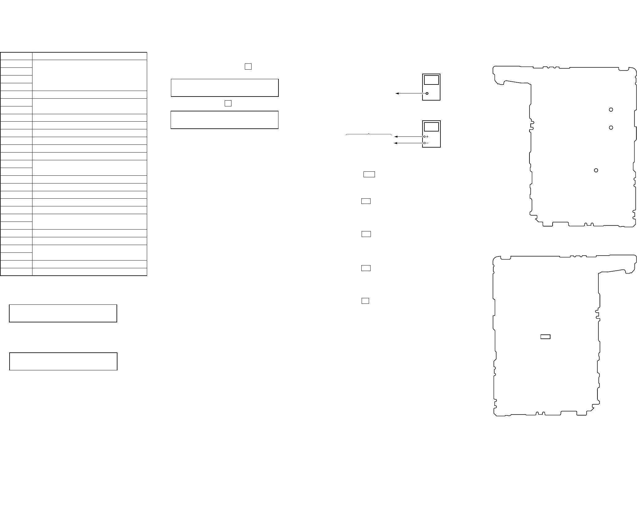
Connection :
Check Method :
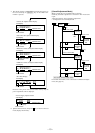
1. Select the manual mode of test mode, and set the laser power
adjusting mode. (mode number 010)
2. Press the . key continuously until the optical pick-up
moves to the most inward track.
3. Open the cover and set the laser power meter on the objective
lens of the optical pick-up.
4. Press the N key, and set the laser MO read adjustment mode.
(mode number 011)
5. Check that the laser power meter reading is 0.81 ± 0.08 mW.
6. Check that the voltage both ends of resitor R1005 at this time
is below 44 mV.
7. Press the N key, and set the laser CD read adjustment
mode. (mode number 012)
8. Check that the laser power meter reading is 0.97 ± 0.10 mW.
9. Check that the voltage both ends of resitor R1005 at this time
is below 44 mV.
10. Press the
N key, and set the laser MO write adjustment mode.
(mode number 013)
11. Check that the laser power meter reading is 4.95 ± 0.50 mW.
12. Check that the voltage both ends of resister R1005 at this time
is below 80 mV.
13. Press the x key.
14. Release the test mode.
digital voltmeter
MAIN board
laser
power meter
Optical pick-up
objective lens
Both ends of R1005
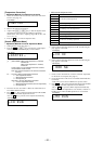
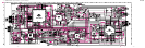
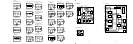
Connecting Location:
– MAIN BOARD (Component Side) –
TP914
(VR)
TP915
(VC)
TP5105
(GND)
– MAIN BOARD (Conductor Side) –
(+)
(–)
R1005
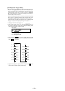
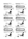
10. If the result of automatic adjustment is OK, the following dis-
play appears in the LCD:
11. If the result of automatic adjustment is NG, the following dis-
play appears in the LCD:
12. If NG, set the manual mode. Perform automatic adjustment
for the items not accepted. (See page 12)
13. To clear the data in overall adjustment mode, set the manual
mode and change the mode number 021 (Res NV) to reset the
NV. (See page 12)
LCD display
MO OK
141
Resume
043
LCD display
ResClr
043
LCD display
### NG
###: Overall adjustment. NG mode number
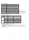
• MO Automatic Adjustment item
Mode No. Description
112
113
MO electrical offset adjustment
114
118
221 Lower reflection CD tracking error gain adjustment
223
Lower reflection CD tracking error offset adjustment
232
236 Lower reflection CD ABCD level adjustment
244 Lower reflection CD focus gain adjustment
245 Lower reflection CD tracking gain adjustment
121 MO tracking error gain adjustment
122 MO tracking error offset adjustment
134 MO TWPP gain adjustment
131
MO double speed read TWPP offset adjustment
132
136 MO ABCD level adjustment
144 MO focus gain adjustment
145 MO tracking gain adjustment
138 MO RF gain adjustment
434 MO write TWPP gain adjustment
431
MO write TWPP offset adjustment
432
436 MO write ABCD level adjustment
445 MO write tracking gain adjustment
411
MO normal speed read TWPP offset adjustment
412
448 32 cluster full recording
141 MO focus bias adjustment
14. When both CD and MO overall adjustments are OK, set the
manual mode and clear the clock data.
For the microprocessor version 1.20 or later, set the mode num-
ber 043 (Resume), and press the X key.
r Press the X key, historical data clear
Note: In step 10, set the clock data to 99Y11M11D11H11M00S,
and in step 14, do not set the clock.
– 22 –
Ver 1.4 2001. 01