


– 3 –
1. GENERAL
Looking at the controls ...................................................... 4
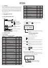
2. SELF-DIAGNOSTIC
2-1. General ............................................................................... 5
2-2. Test Mode Setting .............................................................. 5
2-3. Operation in Test Mode Setting ......................................... 5
2-4. Releasing the Test Mode .................................................... 5
2-5. Self-Diagnostic Mode ........................................................ 5
2-6. Clearing the Error Indication Code
and Total Recording Time .................................................. 6
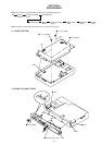
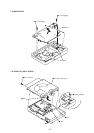
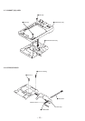
3. DISASSEMBLY
3-1. Panel, Bottom..................................................................... 7
3-2. Panel (SV) Assy, Front....................................................... 7
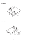
3-3. LCD Module ...................................................................... 8
3-4. Connector ........................................................................... 8
3-5. Main Board ........................................................................ 9
3-6. Panel (SV) Assy, Upper ..................................................... 9
3-7. Cabinet (SV) Assy ........................................................... 10
3-8. OP Block Assy ................................................................. 10
3-9. Holder Assy...................................................................... 11
TABLE OF CONTENTS
4. TEST MODE
4-1. General ............................................................................. 12
4-2. Test Mode Setting ............................................................ 12
4-3. Test Mode Structure ......................................................... 12
4-4. Manual Mode ................................................................... 12
4-5. Overall Adjustment Mode (Assy Mode) .......................... 15
4-6. Hybrid Mode, Key Check Mode ...................................... 16
5. ELECTRICAL ADJUSTMENTS ........................... 17
6. DIAGRAMS
6-1. IC Pin Descriptions .......................................................... 20
6-2. Block Diagram – Servo Section –.................................... 25
6-3. Block Diagram – Audio Section – ................................... 27
6-4. Block Diagram – System Control Section – .................... 29
6-5. Printed Wiring Board ....................................................... 31
6-6. Schematic Diagram – Main Section (1/3) –..................... 35
6-7. Schematic Diagram – Main Section (2/3) –..................... 38
6-8. Schematic Diagram – Main Section (3/3) –..................... 41
7. EXPLODED VIEWS
7-1. Panel Section.................................................................... 49
7-2. Cabinet (SV) Assy Section .............................................. 50
7-3. Mechanism Deck Section ................................................ 51
8. ELECTRICAL PARTS LIST................................... 52
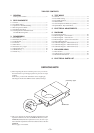
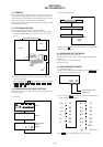
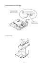
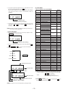
SERVICING NOTE
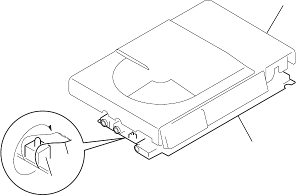
1) When repairing this device with the power on, if you remove
the main board or open the upper panel assy, this device stops
working.
In this case, you can work without the device stopping by
fastening the hook of the OPEN1 switch (S801) with tape.
2) This set is designed to perform automatic adjustment for each
adjustment and write its value to EEPROM. Therefore, when
EEPROM (IC803) has been replaced in service, be sure to per-
form automatic adjustment and write resultant values to the new
EEPROM.
Refer to page 12 for details.
panel assy, uppe
r
MAIN board
tape
S801