


– 17 –
SECTION 5
ELECTRICAL ADJUSTMENTS
PRECAUTIONS FOR ADJUSTMENT
1) Perform all adjustments in the order given in the test mode.
After adjusting, exit the test mode.
2) Use the following tools and measuring instruments.
• Test CD TDYS-1
(Part No. : 4-963-646-01)
• SONY MO disc available on the market
• Laser power meter LPM-8001
(Part No. : J-2501-046-A)
• Oscilloscope (Frequency band above 40 MHz. Perform the
calibration of probe first before measuring.)
• Digital voltmeter
3) Unless specified othewise, supply DC 4.5V from the DC IN 4.5V
jack.
4) Swtich, knob positions
HOLD switch .............. OFF
AVLS switch................ NORM
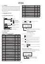
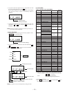
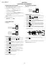
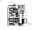
LASER POWER CHECK
Connection :
Adjustment Method :
1. Set the servo mode of the test mode (Mode : 000).
2. Press the ( key, and set the laser power adjustment mode
(Mode : 020) using the VOLUME + or – key.
3. Press the = key and move the optical pick-up to the inner
most circumference.
4. Open the cover and set the laser power meter on the objective
lens of the optical pick-up.
5. Press the ( key, and set the laser CD/MO read adjustment
mode (Mode : 021).
6. Check that the laser power meter reading is 0.85 ± 0.085 mW.
7. Check that the voltage between AP5117 (VCC) and AP574
(LDI0) at this time is below 40 mV.
8. Press the ( key, and set the laser MO write adjustment
mode (Mode : 022).
9. Check that the laser power meter reading is 6.8 ± 0.68 mW.
10. Press the P key to finalize the adjustment data.
11. Check that the voltage between AP5117 (VCC) and AP574
(LDI0) at this time is below 80 mV.
12. Press the p key.
13. Exit the test mode.
Adjustment Location : See page 19.
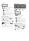
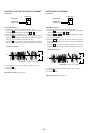
MO TRAVERSE ADJUSTMENT
Connection :
Adjustment Method :
1. Set the servo mode of the test mode (Mode : 000).
2. Press the ( key, and set the MO test adjustment mode (Mode
: 030) using the VOLUME + or – key.
3. Press the = or + key and move the optical pick-up to
the center circumference.
4. Insert any MO disk available on the market.
5. When the ( key is pressed, the MO read EF balance adjust-
ment mode (Mode : 032) will be set after MO focus search
adjustment mode (Mode : 031).
6. Press the P key to perform automatic adjustment, and check
that the traverse waveform is symmetrical at the top and bottom.
7. Slide the REC key and set the MO write EF balance adjust
ment mode (Mode : 034).
8. Press the P key to perform automatic adjustment, and check
that the traverse waveform is symmetrical at the top and bottom.
9. Check that the traverse level at this time is above 1.0 Vp-p.
10. Press the p key.
11. Exit the test mode.
Note) Using a recorded disk in this adjustment will erase the data.
Adjustment Location : See page 19.
digital voltmete
r
MAIN board
AP5117 (VCC)
AP574 (LDI0)
laser
power meter
Optical pick-up
objective lens
oscilloscop
e
MAIN board
SP526 (TE)
AP503 (VC)
A
B
C
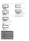
Specification : A = B, C 1.0 Vp-p
0 V
(Traverse waveform)
>
=
Ver 1.4 2001. 01