


– 21 –
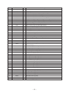
Pin No. Pin name I/O Pin Description
56 AVSS — Ground terminal.
57 PDO — Not used (Open).
58 PCO O Decoder PLL master clock PLL phase comparison output.
59 FILI I Decoder PLL master clock PLL filter input.
60 FILO O Decoder PLL master clock PLL filter output.
61 CLTV I Decoder PLL master clock PLL VCO control voltage input.
62 PEAK I Inputs peak hold signal for light amount signal from RF amplifier (IC501).
63 BOTM I Inputs bottom hold signal for light amount signal from RF amplifier (IC501).
64 ABCD I Light amount signal from RF amplifier (IC501).
65 FE I Input focus error signal from RF amplifier (IC501).
66 AUX1 I Input of auxiliary signal from RF amplifier (IC501).
67 VC I Input of middle point voltage (+1.4 V) from RF amplifier (IC501).
68 ADIO — Not used (Open).
69 AVDD — Power supply (+2.8 V) for analog.
70 ADRT — Not used (Connect to +2.8 V).
71 ADRB — Not used (Connect to ground).
72 AVSS — Ground terminal.
73 SE I Input of sled error signal from RF amplifier (IC501).
74 TE I Input of tracking error signal from RF amplifier (IC501).
75 AUX2 — Not used (Connect to +2.8 V).
76 DCHG — Not used (Connect to +2.8 V).
77 APC — Not used (Connect to +2.8 V).
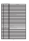
78 ADFG I
Input of ADIP dual FM signal from RF amplifier (IC501) (22.05 kHz ± 1 kHz).
(TTL Schmit input)
79 FO CONT O Focus control output to RF amplifier (IC501).
80 XLRF I Latch signal input from RF amplifier (IC501).
81 CKRF O RFCK clock (7.35 kHz) signal output.
82 DTRF I Serial data input from RF amplifier (IC501).
83 APCREF I Laser power setting signal input.
84 LDDR — Not used (Open).
85 TRDR O Tracking servo drive signal output (–).
86 TFDR O Tracking servo drive signal output (+).
87 DVDD — Power supply (+2.8 V) for digital.
88 FFDR O Focus servo drive signal output (+).
89 FRDR O Focus servo drive signal output (–).
90 FS4 O 176.4 kHz clock signal output (MCLK).
91 SRDR O Sled servo drive signal output (–).
92 SFDR O Sled servo drive signal output (+).
93 SPRD O Spindle servo drive signal output (–).
94 SPFD O Spindle servo drive signal output (+).
95 FGIN I FG signal input from spindle motor driver (IC761).
96 TEST1 — Not used (Connect to ground).
97 TEST2 — Not used (Connect to ground).
98 TEST3 — Not used (Connect to ground).
99 DVSS — Ground terminal.
100 EFMO O EFM recording signal output.