


23
MZ-N1
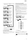
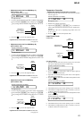
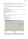
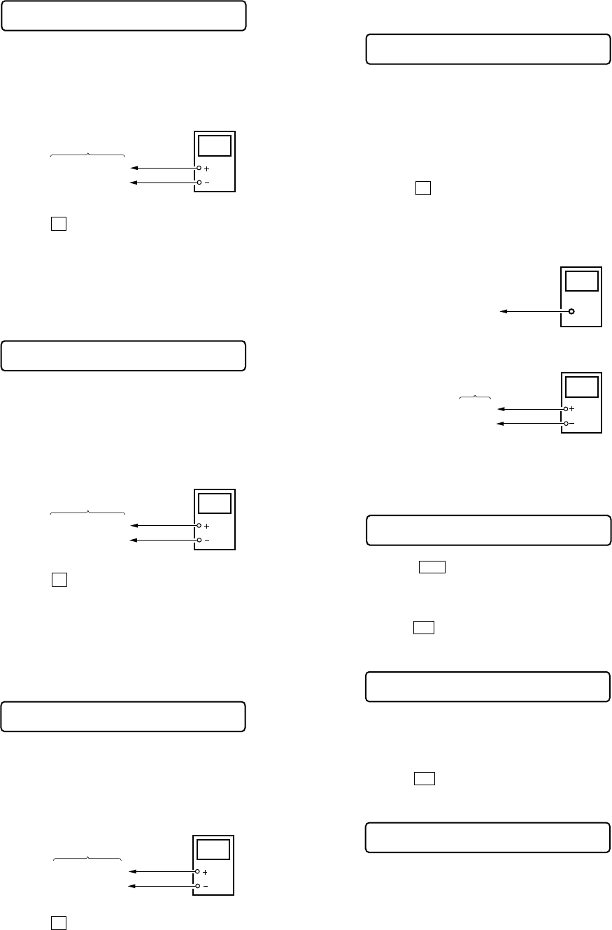
• Adjustment method of Vrec PWM Duty (L)
(item number: 766)
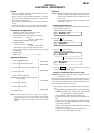
1. Connect a digital voltmeter to the AP611 (VREC) on the MAIN
board, and adjust [VOLUME +] key (voltage up) or [VOLUME
--] key (voltage down) so that the voltage becomes 1.08 V.
2. Press the
X key to write the adjusted value.
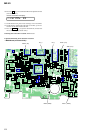
Adjustment and Connection Location:MAIN board
(see page 24)
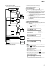
• Adjustment method of Vrec PWM Duty (H)
(item number: 767)
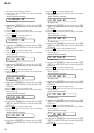
1. Connect a digital voltmeter to the AP611 (VREC) on the MAIN
board, and adjust
[VOLUME +] key (voltage up) or [VOLUME
--] key (voltage down) so that the voltage becomes 1.65 to 1.70
V.
2. Press the
X key to write the adjusted value.
Adjustment and Connection Location:MAIN board
(see page 24)
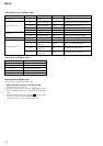
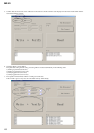
• Adjustment method of Vd PWM Duty
(item number: 768)
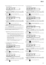
1. Connect a digital voltmeter to the AP911 (VD) on the MAIN
board, and adjust [VOLUME +] key (voltage up) or [VOLUME
--] key (voltage down) so that the voltage becomes 1.31 ± 0.010
V.
2. Press the X key to write the adjusted value.
Adjustment and Connection Location:MAIN board
(see page 24)
digital
voltmeter
MAIN board
AP611 (VREC)
AP912 (GND)
Remote commander LCD display
**
: Adjusted value
RECpwL **
766
+ 0.025
– 0.005
Remote commander LCD display
**
: Adjusted value
RECpwH **
767
digital
voltmeter
MAIN board
AP611 (VREC)
AP912 (GND)
Remote commander LCD display
**
: Adjusted value
VD_PWM **
768
digital
voltmeter
MAIN board
AP911 (VD)
AP912 (GND)
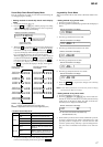
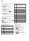
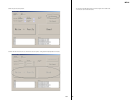
Temperature Correction
• Adjustment method of temperature correction
1. Select the manual mode of test mode, and set the item number
015 (see page 14).
2. Measure the ambient temperature.
3. Adjust with [VOLUME +], [VOLUME --] key so that the ad-
justed value (hexadecimal value) becomes the ambient tem-
perature.
(Initial value: 19h = 25 °C, Adjusting range: 80h to 7fh (–128
°C to +127 °C)
4. Press the X key to write the adjusted value.
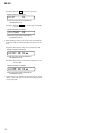
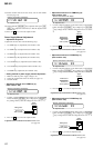
Laser Power Check
Connection :
Checking Method :
1. Select the manual mode of test mode (see page 14), and set the
laser power adjusting mode (item number 010).
2. Press the
. key continuously until the optical pick-up
moves to the most inward track.
3. Open the cover and set the laser power meter on the objective
lens of the optical pick-up.
4. Press the N key, and set the laser MO read adjustment mode
(item number 011).
5. Check that the laser power meter reading is 0.81 ± 0.08 mW.
6. Check that the voltage both ends (TP (+) and TP (–)) of resis-
tor R521 at this time is below 44 mV.
7. Press the N key, and set the laser CD read adjustment mode
(item number 012).
8. Check that the laser power meter reading is 0.97 ± 0.10 mW.
9. Check that the voltage both ends (TP (+) and TP (–)) of resis-
tor R521 at this time is below 44 mV.
Remote commander LCD display
**
: Adjusted value
SetTmp **
015
digital voltmeter
MAIN board
laser
power meter
Optical pick-up
objective lens
TP (+)
TP (–)
Remote commander LCD display
Laser
010
Remote commander LCD display
LrefPw **
011
Remote commander LCD display
HrefPw **
012