


22
MZ-N1
25) Select manual mode of the test mode, and set item number
874 (see page 14).
26) Adjust with the [VOLUME +] key (adjusted value up) or [VOL-
UME --] key (adjusted value down) so that the adjusted value
becomes 05.
27) Press the X key to write the adjusted value.
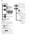
Power Supply Manual Adjustment
• Adjustment sequence
Adjustment must be done with the following steps.
1. Vc PWM Duty (L) adjustment (item number: 762)
r
2. Vc PWM Duty (H) adjustment (item number: 763)
r
3. Vl PWM Duty (L) adjustment (item number: 764)
r
4. Vl PWM Duty (H) adjustment (item number: 765)
r
5. Vrec PWM Duty (L) adjustment (item number: 766)
r
6. Vrec PWM Duty (H) adjustment (item number: 767)
r
7. Vd PWM Duty adjustment (item number: 768)
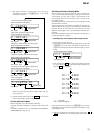
• Setting method of power supply manual adjustment
1. Make sure that the power supply voltage is 3V.
2. Select the manual mode of the test mode (see page 14).
3. Set item number.
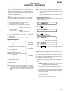
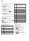
• Adjustment method of Vc PWM Duty (L)
(item number: 762)
1. Connect a digital voltmeter to the AP914 (VC) on the MAIN
board, and adjust
[VOLUME +] key (voltage up) or [VOLUME --]
key (voltage down) so that the voltage becomes 2.40 V.
2. Press the
X key to write the adjusted value.
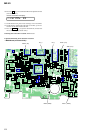
Adjustment and Connection Location:MAIN board
(see page 24)
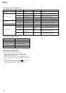
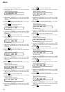
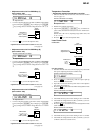
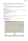
• Adjustment method of Vc PWM Duty (H)
(item number: 763)
1. Connect a digital voltmeter to the AP914 (VC) on the MAIN
board, and adjust
[VOLUME +] key (voltage up) or [VOLUME
--] key (voltage down) so that the voltage becomes 2.75 ± 0.015
V.
2. Press the
X key to write the adjusted value.
Adjustment and Connection Location:MAIN board
(see page 24)
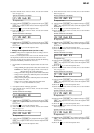
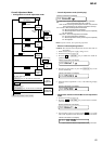
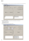
• Adjustment method of Vl PWM Duty (L)
(item number: 764)
1. Connect a digital voltmeter to the AP915 (VL) on the MAIN
board, and adjust
[VOLUME +] key (voltage up) or [VOLUME
--] key (voltage down) so that the voltage becomes 2.30 V.
2. Press the X key to write the adjusted value.
Adjustment and Connection Location:MAIN board
(see page 24)
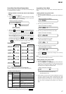
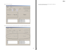
• Adjustment method of Vl PWM Duty (H)
(item number: 765)
1. Connect a digital voltmeter to the AP915 (VL) on the MAIN
board, and adjust [VOLUME +] key (voltage up) or [VOLUME
--] key (voltage down) so that the voltage becomes 2.55 V.
2. Press the X key to write the adjusted value.
Adjustment and Connection Location:MAIN board
(see page 24)
digital
voltmete
r
MAIN board
AP914 (VC)
AP912 (GND)
digital
voltmete
r
MAIN board
AP915 (VL)
AP912 (GND)
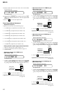
Remote commander LCD display
**
: Adjusted value
VchPWM **
763
+ 0.005
– 0.01
+ 0.005
– 0.01
Remote commander LCD display
**
: Adjusted value
VclPWM **
762
digital
voltmete
r
MAIN board
AP914 (VC)
AP912 (GND)
Remote commander LCD display
**
: Adjusted value
VLpwmL **
764
Remote commander LCD display
**
: Adjusted value
VLpwmH **
765
+ 0.005
– 0.01
digital
voltmeter
MAIN board
AP915 (VL)
AP912 (GND)
Remote commander LCD display
**
: Adjusted value
V6 dat **
874