


– 9 –
[]
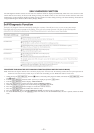
RETRY CAUSE DISPLAY MODE
• In this test mode, the causes for retry of the unit during recording can be displayed on the fluorescent indicator tube. During playback,
the “track mode” for obtaining track information will be set.
This is useful for locating the faulty part of the unit.
• The following will be displayed :
During recording and stop: Retry cause, number of retries, and number of retry errors.
During playback : Information such as type of disc played, part played, copyright.
These are displayed in hexadecimal.
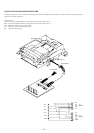
Procedure:
1. Load a recordable disc whose contents can be erased into the unit.
2. Press the [MENU/NO] button. When “Edit Menu” is displayed on the fluorescent indicator tube, turn the [AMS] knob to
display “All Erase?”.
3. Press the [YES] button. (Or press the [AMS] knob)
4. When “All Erase??” is displayed on the fluorescent indicator tube, the music calendar number blinks.
5. Press the [YES]button to display “Complete!!”, and press the p button immediately. Wait for about 15 seconds while pressing the
button. (The [AMS] knob can be pressed instead of the [YES]button for the same results)
6. When the “TOC” displayed on the fluorescent display tube goes off, release the p button.
7. Press the [REC] button to start recording. Then press the P button and start recording.
8. To check the “track mode”, press the · button to start play.
9. To release the test mode, press the 1/u button, and turn OFF the power. When “TOC” disappears, disconnect the power plug from the
outlet.
r
[]
[]
[]
[]
±
≠
±
≠
±
≠
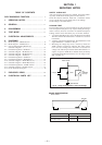
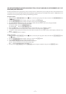
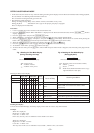
Fig. 1 Reading the Test Mode Display
(During recording and stop)
RTs@@c##e
**
Fluorescent indicator tube display
@@ : Cause of retry
## : Number of retries
**
: Number of retry errors
Fig. 2 Reading the Test Mode Display
(During playback)
@@####
**
$$
Fluorescent indicator tube display
@@ : Parts No. (name of area named on TOC)
## : Cluster
**
: Sector
$$ : Track mode (Track information such as copy-
right information of each part)
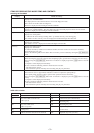
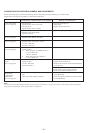
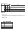
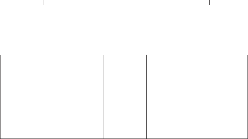
Reading the Retry Cause Display
84218421
b7 b6 b5 b4 b3 b2 b1 b0
00000001
00000010
00000100
00001000
00010000
00100000
01000000
10000000
Hexa-
decimal
Cause of Retry
01
02
04
08
10
20
40
80
Higher Bits Lower Bits
Hexadecimal
Bit
Binary
shock
ader5
Discontinuous address
DIN unlock
FCS incorrect
IVR rec error
CLV unlock
Access fault
Occurring conditions
When track jump (shock) is detected
When ADER was counted more than five times
continuously
When ADIP address is not continuous
When DIN unlock is detected
When not in focus
When ABCD signal level exceeds the specified range
When CLV is unlocked
When access operation is not performed normally
Reading the Display:
Convert the hexadecimal display into binary display. If more than two causes, they will be added.
Example
When 42 is displayed:
Higher bit: 4 = 0100 n b6
Lower bit : 2 = 0010 n b1
In this case, the retry cause is combined of “CLV unlock” and “ader5”.
When A2 is displayed:
Higher bit: A = 1010 n b7+b5
Lower bit : 2 = 0010 n b1
The retry cause in this case is combined of “access fault”, “IVR rec error”, and “ader5”.
Address